Do you have a question about the Mitsubishi PUHY-EP250 and is the answer not in the manual?
Essential safety measures for handling and operating the air conditioner.
Precautions for safe transportation and installation of the unit.
Guidelines for the correct and safe installation of the unit.
Safety measures for refrigerant piping procedures.
Safety guidelines for electrical wiring and connections.
Safety instructions for unit relocation and repair procedures.
Further precautions for installation, inspection, and operation.
Steps to take before starting piping installation.
Guidance on piping materials, refrigerants, and oils.
Procedures for brazing, leak testing, and charging refrigerant.
Compatible combinations of indoor and outdoor units.
Specifications for control wiring types and maximum lengths.
Configuring system settings using dipswitches.
Procedures for setting M-NET addresses for system components.
How demand control functions operate and are configured.
Illustrative examples of system connection configurations.
Wiring and configuration examples for systems using MA remote controllers.
Wiring and configuration examples for systems using ME remote controllers.
Examples for systems using both MA and ME remote controllers.
Guidelines for refrigerant pipe length and diameter restrictions.
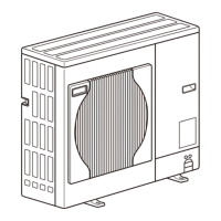
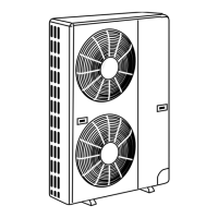
Visual identification of outdoor unit parts and refrigerant circuit.
Schematic diagrams of outdoor unit refrigerant circuits.
Detailed explanation of the functions of major outdoor unit components.
Detailed explanation of the functions of major indoor unit components.
Layout and arrangement of circuit boards within the outdoor unit.
Identification of components on the outdoor unit circuit boards.
Electrical wiring diagrams for outdoor units.
Wiring diagrams specific to the transmission booster.
Configuration settings via dipswitches and default factory settings.
Detailed control mechanisms for outdoor units, including protection and operation modes.
Visual flowcharts illustrating operational sequences and logic.
Essential checks and precautions before performing a test run.
Comparison of features and specifications for MA and ME remote controllers.
Steps to configure group and interlock settings using ME remote controller.
Guide to selecting various functions available on the ME remote controller.
Procedures for setting up interlocks with LOSSNAY units using MA remote controller.
How to select the sensor used for room temperature detection.
Detailed methods for performing test runs with remote controllers.
Understanding system performance related to refrigerant charge.
Procedures for assessing and adjusting refrigerant levels.
Identification of normal operating symptoms that may appear unusual.
Reference data for system operating parameters.
Lists of all error codes and their preliminary identification.
Explanations and solutions for error codes 0-999.
Explanations and solutions for error codes 1000-1999.
Explanations and solutions for error codes 2000-2999.
Explanations and solutions for error codes 3000-3999.
Explanations and solutions for error codes 4000-4999.
Explanations and solutions for error codes 5000-5999.
Explanations and solutions for error codes 6000-6999.
Explanations and solutions for error codes 7000-7999.
Specific troubleshooting steps for MA remote controller issues.
Specific troubleshooting steps for ME remote controller issues.
Diagnosing and resolving issues with refrigerant flow and control.
Analyzing transmission signals and identifying electrical noise.
Understanding pressure sensor circuits and troubleshooting related faults.
Diagnosing and resolving issues with solenoid valves.
Troubleshooting issues related to the outdoor unit's fan motor and operation.
Diagnosing and resolving problems with Linear Expansion Valves (LEVs).
Troubleshooting issues specific to the inverter circuit and components.
Overview and troubleshooting of the unit's control circuit.
Procedures for detecting and addressing refrigerant leaks.
Step-by-step guide for replacing the compressor unit.
Using LED indicators on the outdoor unit to diagnose problems.
General overview of LED status indicators and how to read them.
A table mapping LED patterns to specific statuses and errors.
| Cooling Capacity | 28.0 kW |
|---|---|
| Heating Capacity | 31.5 kW |
| Refrigerant | R410A |
| Series | City Multi |
| Type | Heat Pump |
| Power Supply | 380-415V, 50Hz, 3-Phase |
| Operating Temperature Range (Cooling) | -5°C to 46°C DB |
| Operating Temperature Range (Heating) | -20°C to 15.5°C WB |
