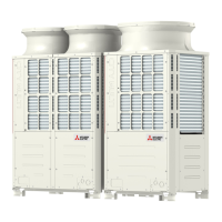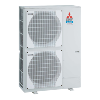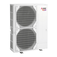
Do you have a question about the Mitsubishi PUHY-P250YJM-A and is the answer not in the manual?
| Brand | Mitsubishi |
|---|---|
| Model | PUHY-P250YJM-A |
| Category | Air Conditioner |
| Language | English |
Essential safety instructions, warnings, and cautions to prevent injury or death.
Safety measures for refrigerant types, installation, and leak prevention.
Guidelines for proper grounding, wiring, circuit breakers, and avoiding electrical hazards.
Critical safety steps before initial unit operation, including power and component handling.
Steps for refrigerant check, safety review, and necessary tools for servicing R410A systems.
Details on R410A piping materials, processing, brazing, and leak testing procedures.
Procedures for refrigerant charging and steps to address leaks, including refrigerant characteristics.
Information on refrigerating oil compatibility and the impact of contaminants in HFC systems.
Rules for system setup, connecting indoor/outdoor units, and controller compatibility.
Requirements for transmission and remote controller cable types and maximum allowable lengths.
Procedures for setting DIP switches, system addresses, and controller connections.
Guidelines for maximum allowable refrigerant pipe lengths and height differences.
Identification of external components and the refrigerant circuit diagram of the outdoor unit.
Details on the control box, M-NET board, INV board, and fan board within the outdoor unit.
Dimensional data and connection port locations for PFD-P250VM-E and PFD-P500VM-E models.
Views of internal components including fans, controllers, drain systems, and heat exchangers.
Layout of components within the indoor unit's control box and the indoor control board.
Step-by-step guide for disassembling the top and bottom sections of indoor units.
Detailed wiring diagram for the PUHY-P250YJM-A outdoor unit, illustrating component connections.
Wiring diagrams for PFD-P250VM-E and PFD-P500VM-E indoor units, showing control board connections.
Visual diagrams of refrigerant flow for single and multiple refrigerant circuit systems.
Detailed descriptions of outdoor and indoor unit parts and their roles in the refrigerant circuit.
Explanation of dipswitch functions and factory settings on outdoor and indoor control boards.
Control mechanisms for outdoor units, including startup sequence, bypass, and compressor frequency.
Control functions for indoor units, covering thermostat, actuators, and emergency modes.
Visual flowcharts detailing cooling, heating, and defrost operations for indoor and outdoor units.
Essential checks for leaks, wiring, valves, and power before conducting a test run.
Step-by-step instructions for performing test runs on refrigerant circuits and system operation.
Procedures for adjusting refrigerant, identifying charging issues, and calculation formulas.
Steps for setting up and initializing system rotation control for backup unit operation.
Comprehensive list of error codes, definitions, and troubleshooting applicability for units.
Procedures for responding to error messages displayed on the remote controller.
Detailed troubleshooting for key parts like sensors, valves, fans, and power circuits.
Methods for identifying and repairing refrigerant leaks in indoor and outdoor units.
Step-by-step instructions for replacing compressor, fan motor, and bearings.
Interpretation of LED error displays on the outdoor unit control board for effective troubleshooting.
Guide to understanding numerical and flag displays on the 7-segment LED service monitor.
Tables correlating SW settings with displayed operational data, error codes, and unit status.
