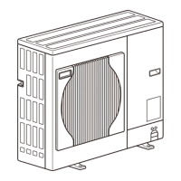
[ VI Refrigerant Circuit ]
- 73 -
HWE1018A GB
2. Indoor unit
Part
name
Symbols
(functions)
Notes Usage Specifications Check method
Linear ex-
pansion
valve
(LEV)
LEV 1) Adjusts superheat at the
heat exchanger outlet of the
indoor unit during cooling
2) Adjusts subcool at the heat
exchanger outlet of the in-
door unit during heating
DC12V
Opening of a valve driven by
a stepping motor
0-(2000) pulses
Continuity check
with a tester
Continuity be-
tween white, red,
and orange.
Continuity be-
tween yellow,
brown, and blue.
Thermis-
tor
TH21
(Suction
air tem-
perature)
Indoor unit control (Thermo)
0°C[32°F] : 15kohm
10°C[50°F] :9.7kohm
20°C[68°F] :6.4kohm
25°C[77°F] :5.3kohm
30°C[86°F]:4.3kohm
40°C[104°F] :3.1kohm
Resistance check
TH22
(Pipe tem-
perature)
Indoor unit control (Freeze pre-
vention, Pre-heating stand-by)
TH23
(Gas pipe
tempera-
ture)
LEV control during cooling oper-
ation (Superheat detection)
TH24
(Dis-
charge air
tempera-
ture)
Controls indoor unit discharge
(thermostat)
Float
Switch
33P1 Detects drain pan water level Contact Resistance:
Under 250 mohm
B contact type
Continuity check
with a tester
33P2 P500
model
only
Motor MF Sends air PFD-P250VM-E
AC380~415V Type E 4P
Output 3.7kW
Rotation number
check
Standard 930rpm
PFD-P500VM-E
AC380~415V Type B 4P
Output 5.5kW
Rotation number
check
Standard 978rpm
 Loading...
