EasyManua.ls Logo

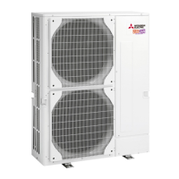
Mitsubishi PUHZ-SW75VHAPUHZ-SW100VHAPUHZ-SW100YHAPUHZ-SW120VHAPUHZ-SW120YHAPUHZ-SW75VHA-BSPUHZ-SW100VHA-BSPUHZ-SW100YHA-BSPUHZ-SW12 User Manual

Mitsubishi PUHZ-SW75VHAPUHZ-SW100VHAPUHZ-SW100YHAPUHZ-SW120VHAPUHZ-SW120YHAPUHZ-SW75VHA-BSPUHZ-SW100VHA-BSPUHZ-SW100YHA-BSPUHZ-SW12
100 pages
To Next Page IconTo Next Page
Page #1 background imageLoading...
Page #1 background image
SERVICE MANUAL
CONTENTS
1. TECHNICAL CHANGES
................................
2
2. REFERENCE MANUAL
.................................
3
3. SAFETY PRECAUTION
.................................
4
4. FEATURES
.....................................................
8
5. SPECIFICATIONS
..........................................
9
6. DATA
.............................................................
13
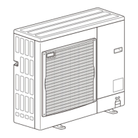
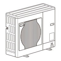
7. OUTLINES AND DIMENSIONS
...................
15
8. WIRING DIAGRAM
......................................
17
9. WIRING SPECIFICATIONS
..........................
24
10.
REFRIGERANT SYSTEM DIAGRAM
..............
25
11. TROUBLESHOOTING
..................................
27
12. DISASSEMBLY PROCEDURE
.....................
82
R410A
PUHZ-SW75VHA.UK
PUHZ-SW75VHA-BS.UK
Salt proof model
PUHZ-SW75VHA-BS
PUHZ-SW100VHA-BS
PUHZ-SW100YHA-BS
PUHZ-SW120VHA-BS
PUHZ-SW120YHA-BS
Note:
This manual describes
service data of the outdoor
units only.
PUHZ-SW75VHA-BS.UK PUHZ-SW75VHAR3-BS.UK
PUHZ-SW75VHAR4-BS.UK
PUHZ-SW100VHA-BS.UK PUHZ-SW100VHAR3-BS.UK
PUHZ-SW100VHAR4-BS.UK
PUHZ-SW100YHA-BS.UK PUHZ-SW100YHAR1-BS.UK
PUHZ-SW100YHAR3-BS.UK PUHZ-SW100YHAR4-BS.UK
PUHZ-SW120VHA-BS.UK PUHZ-SW120VHAR3-BS.UK
PUHZ-SW120VHAR4-BS.UK
PUHZ-SW120YHA-BS.UK PUHZ-SW120YHAR1-BS.UK
PUHZ-SW120YHAR3-BS.UK PUHZ-SW120YHAR4-BS.UK
Outdoor unit
[Model Name]
PUHZ-SW75VHA
PUHZ-SW100VHA
PUHZ-SW100YHA
PUHZ-SW120VHA
PUHZ-SW120YHA
[Service ref.]
PUHZ-SW75VHA.UK PUHZ-SW75VHAR3.UK
PUHZ-SW75VHAR4.UK
PUHZ-SW100VHA.UK PUHZ-SW100VHAR3.UK
PUHZ-SW100VHAR4.UK
PUHZ-SW100YHA.UK PUHZ-SW100YHAR1.UK
PUHZ-SW100YHAR3.UK PUHZ-SW100YHAR4.UK
PUHZ-SW120VHA.UK PUHZ-SW120VHAR3.UK
PUHZ-SW120VHAR4.UK
PUHZ-SW120YHA.UK PUHZ-SW120YHAR1.UK
PUHZ-SW120YHAR3.UK PUHZ-SW120YHAR4.UK
PARTS CATALOG (OCB533)
Revision:
Added
PUHZ-SW75VHAR4.UK,
PUHZ-SW75VHAR4-BS.UK,
PUHZ-SW100VHAR4.UK,
PUHZ-SW100VHAR4-BS.UK,
PUHZ-SW100YHAR4.UK,
PUHZ-SW100YHAR4-BS.UK,
PUHZ-SW120VHAR4.UK,
PUHZ-SW120VHAR4-BS. UK,
PUHZ-SW120YHAR4.UK and
PUHZ-SW120YHAR4-BS.UK
in REVISED EDITION-D.
Some descriptions have
been modified.
Please void OCH533
REVISED EDITION-C.
No. OCH533
REVISED EDITION-D
August 2015
SPLIT-TYPE, AIR TO WATER HEAT PUMP
Questions and Answers:

Mitsubishi PUHZ-SW75VHAPUHZ-SW100VHAPUHZ-SW100YHAPUHZ-SW120VHAPUHZ-SW120YHAPUHZ-SW75VHA-BSPUHZ-SW100VHA-BSPUHZ-SW100YHA-BSPUHZ-SW12 Specifications

General IconGeneral
BrandMitsubishi
ModelPUHZ-SW75VHAPUHZ-SW100VHAPUHZ-SW100YHAPUHZ-SW120VHAPUHZ-SW120YHAPUHZ-SW75VHA-BSPUHZ-SW100VHA-BSPUHZ-SW100YHA-BSPUHZ-SW12
CategoryAir Conditioner
LanguageEnglish

Summary

TECHNICAL CHANGES

REFERENCE MANUAL

SAFETY PRECAUTION

ALWAYS OBSERVE FOR SAFETY

General safety rules to follow before and during repair service.

CAUTIONS RELATED TO NEW REFRIGERANT

Specific warnings and practices for using R410A refrigerant.

Service tools

Lists essential tools required for servicing R410A systems.

PRECAUTIONS WHEN REUSING EXISTING R22 REFRIGERANT PIPES

Guidelines for safely reusing existing R22 refrigerant piping.

PRECAUTIONS FOR SALT PROOF TYPE "-BS" MODEL

Specific installation and maintenance advice for salt-resistant models.

Cautions for refrigerant piping work

Important considerations for handling R410A refrigerant piping.

FEATURES

CHARGELESS SYSTEM

Explains the pre-charged refrigerant system for simplified installation.

SPECIFICATIONS

Rating conditions

Lists operational parameters and performance at various conditions.

DATA

REFILLING REFRIGERANT CHARGE (R410A : kg)

Table showing refrigerant charge amounts based on piping length.

COMPRESSOR TECHNICAL DATA

Technical specifications for the compressor, including winding resistance.

NOISE CRITERION CURVES

Graphical representation of noise levels across different frequencies.

OUTLINES AND DIMENSIONS

FREE SPACE (Around the unit)

Recommended clearance space required around the outdoor unit.

SERVICE SPACE

Space needed for accessing the unit for maintenance and service.

FOUNDATION BOLTS

Information on securing the unit with foundation bolts.

PIPING-WIRING DIRECTIONS

Details on the directions from which piping and wiring can be connected.

WIRING DIAGRAM

WIRING SPECIFICATIONS

FIELD ELECTRICAL WIRING (power wiring specifications)

Detailed power wiring specifications based on outdoor unit model.

REFRIGERANT SYSTEM DIAGRAM

REFRIGERANT COLLECTING (PUMP DOWN)

Procedure for safely collecting refrigerant before servicing or disposal.

UNIT REPLACEMENT OPERATION

Steps for replacing existing pipes when installing new units.

TROUBLESHOOTING

TROUBLESHOOTING

General approach to interpreting self-diagnosis codes and taking action.

SELF-DIAGNOSIS ACTION TABLE

Detailed table linking error codes to abnormal points and corrective actions.

HOW TO CHECK THE PARTS

Instructions for testing the resistance of various electronic components.

Check method of DC fan motor (fan motor/outdoor controller circuit board)

Procedure for diagnosing DC fan motor and related circuit board issues.

HOW TO CHECK THE COMPONENTS

Step-by-step guide for checking specific components like sensors and motors.

Linear expansion valve

Description of the linear expansion valve's operation and checking procedure.

TEST POINT DIAGRAM

Diagram showing crucial test points on the outdoor controller circuit board.

Outdoor converter circuit board

FUNCTION OF SWITCHES, CONNECTORS AND JUMPERS

Special function

Details on special operational modes like low-level sound priority.

<Display function of inspection for outdoor unit>

How to interpret LED indicators for unit status and error codes.

Request code list

Detail Contents in Request Code

Provides detailed explanations for various request codes displayed by the unit.

DISASSEMBLY PROCEDURE

Related product manuals