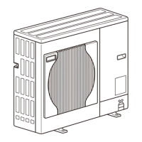
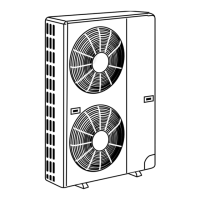
[2-3 Switch Settings ]
- 19 -
HWE12050 GB
2 Restrictions
2) Remote controller wiring
*1 MA remote controller refers to MA remote controller (PAR-31MAA, PAR-21MAA), MA simple remote controller, and
wireless remote controller.
*2 ME remote controller refers to ME remote controller and ME simple remote controller.
*3 The use of cables that are smaller than 0.75mm
2
(AWG18) is recommended for easy handling.
*4 When connected to the terminal block on the Simple remote controller, use cables that meet the cable size specifi-
cations shown in the parenthesis.
*5 When connecting PAR-31MAA or MA Simple remote controller, use sheathed cables with a minimum thickness of
0.3 mm
2
.
2-3 Switch Settings
1. Switch setting
The necessary switch settings depend on system configuration. Before performing wiring work, refer to the following page(s).
[2-7 Example System with an MA Remote Controller](page 30)
[2-8 Example System with an ME Remote Controller](page 40)
[2-9 Example System with an MA and an ME Remote Controller](page 42)
If the switch settings are changed while the unit is being powered, those changes will not take effect, and the unit will not
function properly.
*1. Applicable when LOSSNAY units are connected to the indoor-outdoor transmission line.
*2. The outdoor units in the same refrigerant circuit are automatically designated as OC, OS1, and OS2 in the order of
capacity from large to small (if two or more units have the same capacity, in the order of address from small to large).
*3. Turn off the power to all the outdoor units in the same refrigerant circuit.
*4. When a PAR-31MAA is connected to a group, no other MA remote controllers can be connected to the same group.
*5. When setting the switch SW4 of the control board, set it with the outdoor unit power on. Refer to the following page(s).
[5-1-1 Outdoor Unit Switch Functions and Factory Settings](page 77)
MA remote controller
*1
ME remote controller
*2
Cable type
Type CVV CVV
Number of
cores
2-core cable 2-core cable
Cable size
0.3 to 1.25mm
2 *3 *5
[AWG22 to 16]
0.3 to 1.25mm
2 *3
[AWG22 to 16]
(0.75 to 1.25mm
2
)
*4
[AWG18 to 16]
Maximum overall line
length
200 m [656ft] max.
The section of the cable that exceeds 10m
[32ft] must be included in the maximum in-
door-outdoor transmission line distance.
Units on which to set the switches Symbol Units to which the power must be shut off
CITY MULTI indoor unit Main/sub unit IC Outdoor units
*3
and Indoor units
LOSSNAY, OA processing unit
*1
LC Outdoor units
*3
and LOSSNAY
ATW Booster Unit BU Outdoor units and Booster Unit
Water Hex Unit AU Outdoor units and Water Hex Unit
Air handling kit IC Outdoor units
*3
or field supplied air handling
unit
ME remote controller Main/sub remote
controller
RC Outdoor units
*3
MA remote controller
*4
Main/sub remote
controller
MA Indoor units
CITY MULTI outdoor unit
*2
OC,OS1,OS2 Outdoor units
*3 *5
 Loading...
