
Do you have a question about the Mitsubishi PUMY-P125YHM and is the answer not in the manual?
| Brand | Mitsubishi |
|---|---|
| Model | PUMY-P125YHM |
| Category | Air Conditioner |
| Language | English |
Details on modifications made to models, including compressor, oil, and electrical parts.
Cautions for units utilizing refrigerant R410A, covering piping, vacuum pumps, and tools.
General guidelines for performing service, including refrigerant recovery and filter drier usage.
Procedure for charging refrigerant directly from a cylinder.
List of exclusive service tools required for R410A refrigerant.
Guidelines for maintaining salt resistance in "-BS" model units.
Table indicating compatibility of R410A tools with R22/R407C tools.
Details on outdoor unit capacities, connected indoor units, and branching components.
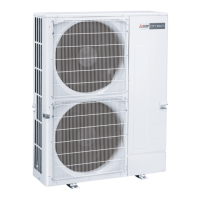
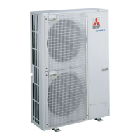
Specifications for PUMY-P series outdoor units, including capacity and motor.
Explanation of model naming conventions for indoor and outdoor units.
Defines cooling and heating operating temperature ranges for indoor and outdoor units.
Methods for calculating system and indoor unit capacities based on connected units.
Table providing standard capacity data for various total indoor unit capacities.
Adjusting capacity based on air conditions, piping length, and defrosting.
Octave band sound pressure levels for PUMY series outdoor units.
Recommended clearance around the outdoor unit for installation and service.
Specifications for securing the unit using foundation bolts.
Possible directions for making piping and wiring connections.
Diagram showing knockout hole locations for piping and wiring.
Wiring diagrams and critical servicing cautions for outdoor units.
Overview of the self-diagnosis function using switches and LEDs on the outdoor unit.
Guidelines for setting up transmission wiring and addresses for system communication.
Schematic representation of the refrigerant flow within the system.
Wiring and address setting examples for M-NET and MA remote control systems.
Procedures and checks required before performing a test run of the system.
Setting up group and paired operations for M-NET remote controllers.
Table of error codes, their causes, and corrective measures during test runs.
Interpreting self-diagnosis results for MA remote controllers and identifying potential issues.
Troubleshooting common issues with M-NET and MA remote controllers.
Symptoms that do not represent system malfunction or emergency conditions.
Table detailing functions and settings for internal DIP switches on the outdoor unit.
Diagrams and pinouts for key outdoor unit connectors and DIP switch functions.
Methods for checking the condition of key components like thermistors and motors.
Feature charts and diagrams for checking thermistors and pressure sensors.
Diagrams indicating test points on the outdoor unit's circuit boards.
Table mapping SW1 settings to displayed outdoor unit functions and operational data.
General guidelines for power wiring, including wire sizing and safety precautions.
Information on wire sizing and main power switch capacity requirements.
Selection criteria for control wires based on remote controllers and system links.
Procedures for assigning identification numbers (addresses) using system switches.
Example wiring diagram for a basic system using an M-NET remote controller.
Formulas for calculating electrical characteristics for power company applications.
Details on refrigerant piping diameters, branch kits, and system layout.
Guidance on selecting appropriate branch kits based on piping configuration.
Method for calculating additional refrigerant charge based on total piping length.
Safety guidelines for R410A refrigerant and maximum concentration limits.
Steps for removing service panels, top panel, and fan motor components.
Steps for disconnecting connectors and removing the electrical parts box.
Procedure for removing low pressure saturated and outdoor temperature thermistors.
Steps for removing the 4-way valve coil, 4-way valve, and bypass valve.
Procedure for removing high/low pressure switches and high pressure sensor.
Steps for removing reactors, compressor, and associated pipes.
Procedure for removing the accumulator and its associated pipes.
List of structural components of the outdoor unit, including part numbers and quantities.
List of functional RoHS compliant parts for the outdoor unit.
List of structural RoHS compliant parts for the outdoor unit.


 Loading...