11 - 3 11 - 3
MELSEC-Q
11 I/O MODULE TROUBLESHOOTING
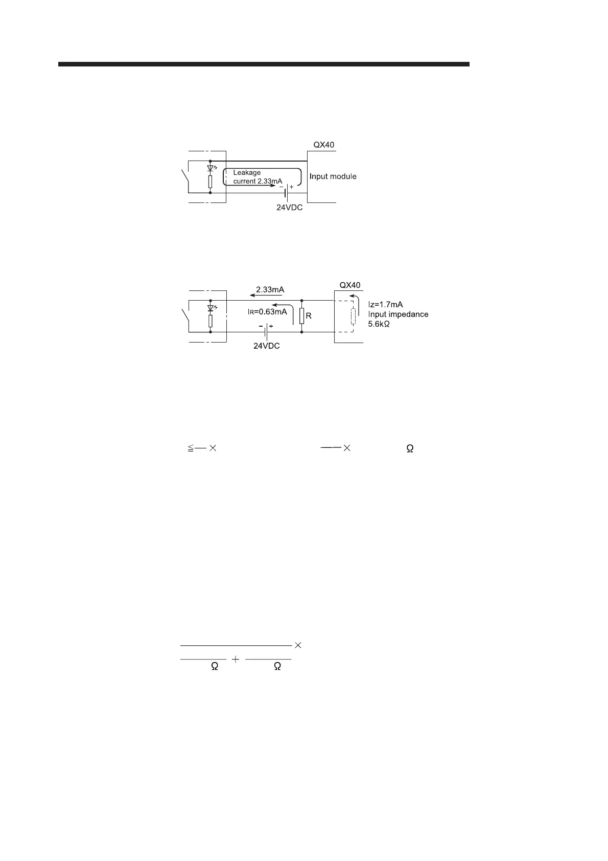
<Calculation example of Example 4>
Connecting a switch with LED display, in which a maximum 2.33mA leakage current
flows when 24VDC is supplied to the QX40.
(1) In this case, the circuit does not satisfy the condition that the OFF current of the
QX40 is 1.7mA or less.
Connect a resistance as follows.
(2) In order to satisfy the condition that the OFF current of the QX40 is 1.7mA or less,
the resistance R, in which a 0.63mA or more current flows, shall be connected.
Calculating with the formula,
the resistance R will be R<15.11kΩ.
Consequently, if the resistance R is set to 12kΩ, the electric power W of the
resistance R will be calculated in the following formula,
W= (Input voltage)
2
/R=28.8
2
/12000=0.069[W].
(3) Since the resistance requires the electric power which is 3 to 5 times of the power
actually consumed, the resistance to be connected to the corresponding terminal
shall be 12.0kΩ and 1/4 to 1[W].
(4) The OFF voltage of the QX40 when the resistance R calculated above is connected
will be 8.90[V]
.
This also satisfies the condition that the OFF voltage of the QX40 is 11V or less.
I
R
: I
Z=
Z (Input impedance): R
R Z (Input impedance) = 5.6=15.11[k ]
0.63
1.7
I
R
I
Z
1
12.0[k ] 5.6[k ]
2.33[mA]=8.90[V]
1
1
 Loading...