11 - 7 11 - 7
MELSEC-Q
11 I/O MODULE TROUBLESHOOTING
Table 11.2 Output Circuit Problems and Corrective Actions (Continued)
Condition Cause Corrective action
Example 5
The load
momentarily
turns on
when the
system is
powered off
(transistor
output).
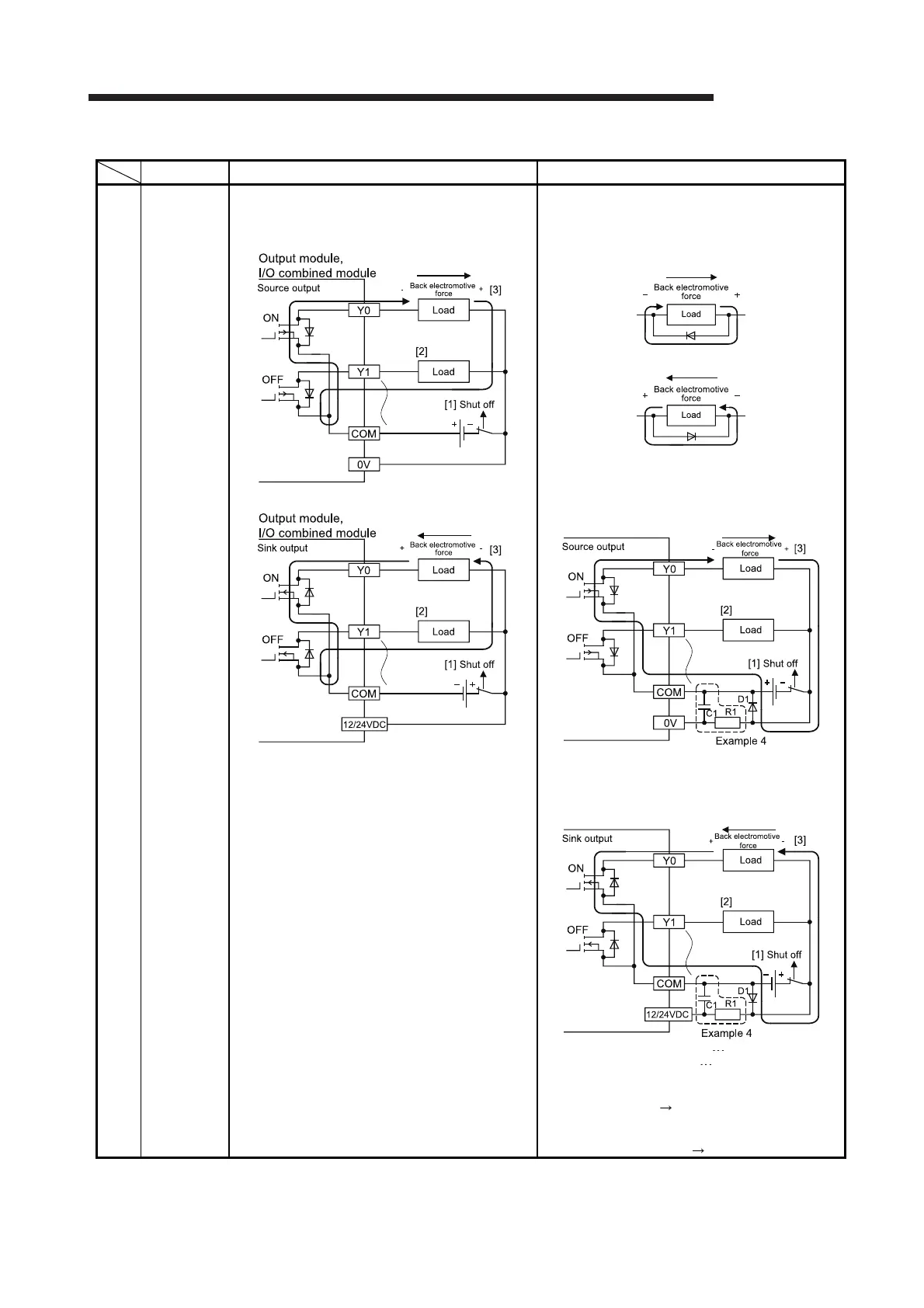
If an inductive load is connected, the load may turn on
from off ([2]) due to back electromotive force at the
time of power-off ([1]).
Take one of the following actions.
(1) To suppress back electromotive force, connect a
diode in parallel with the load where the back
electromotive force has been generated.
Source output
[3]
Sink output
[3]
(2) Configure another current path by connecting a
diode across positive and negative of the external
power supply.
When the corrective action described in the
example 4 is taken at the same time, connect a
diode in parallel with C1 and R1.
* The measures are ineffective in the following
modules due to the characteristic of the external
power supply circuit
QY81P
QY82P
D1: Reverse voltage VR(VRM) *1,
Forward current IF(IFM) *2
*1 Approximately 10 times higher than the rated
voltage in the specifications
Example: 24 VDC Approximately 200V
*2 Two times or more as much as the maximum load
current (common) in the specifications
Example: 2A/1 common 4A or more
(To the next page)
 Loading...