-
224
-
'16 • SCM-T-199
Replace and set up the PCB according to this instruction.
a) Set to an appropriate address and function using switch on PCB.
Select the same setting with the removed PCB.
b) Set to an appropriate capacity using the model selector switch(SW6).
Select the same capacity with the PCB removed from the unit.
c) Replace the PCB
i) Fix the PCB so as not to pitch the cords.
ii) Connect connectors to the PCB. Connect a cable connector with the PCB connector of the same color.
iii) Do not pass CPU surrounding about wirings.
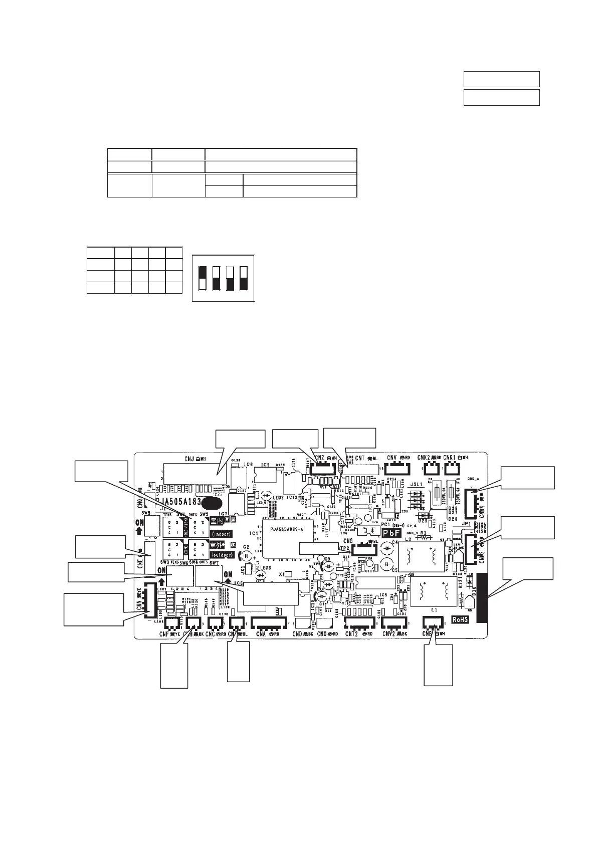
d) Control PCB
Parts mounting are different by the kind of PCB.
Part number
SW2 (Blue)
Address setting
SW7
CNT(Blue)
External switch
CNJ(White)
Louver motor
CNN(Yellow)
Thermistor
(Heat exchanger)
CNI(Blue)
Float SW
CNH(Black)
Thermistor
(Return air)
CNW3(Red)
Power PCB
CNB(White)
Remote
control
CNZ(White)
HA
CNE(White)
RAM checker
CNW4(Blue)
Power PCB
SW6
Capacity setting
Switch
OFF
ON
Plural indoor units control by 1 remote control
Test run SW7-1
Operation check/drain motor test run
SW6
ON
1 2 3 4
Example setting fro 25VF
SW6 -1 -2 -3 -4
25VF
ON
ON
OFF
OFF
OFF
35VF
OFF
OFF OFF
OFF ON
50VF
ON OFF
(i) FDTC series
1) Control PCB
PSB012D976B
PSB012D976C
 Loading...