-
225
-
'16 • SCM-T-199
2) Power PCB
PSB012D953A
This PCB is a general PCB. Replace the PCB according to this instruction.
a)
Replace the PCB
i)
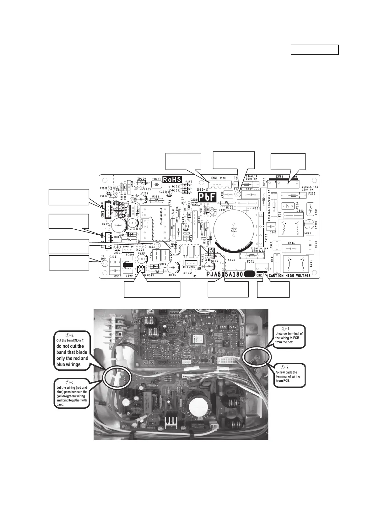
Unscrew terminal of the wiring(yellow/green) soldered to PCB from the box.
ii)
Cut the band that binds the wiring (red and blue) from connector CNW1 and CNW2, and the wiring (yellow/green) from PCB (T2/T3) . (Note 1)
(However, do not cut the band that binds only the red and blue wirings.)
iii)
Replace the PCB only after all the wirings connected to the connector are removed.
iv)
Fix the board such that it will not pinch any of the wires.
v)
Reconnect the wirings to the PCB. Wiring connector color should match with the color of connector of the PCB. (Note 2)
vi)
Let the wiring (red and blue) pass beneath the (yellow/green) wiring and bind together with band.
vii)
Screw back the terminal of wiring (yellow/green) from PCB(T1,T2/T3), that was removed in
i)
.
In that case, do not place the crimping part of the wiring under the PCB.
(Note 1): It might not be applicable on some models.
(Note 2): After replacing PCB, connection between capacitor assy and connector CNP is no longer needed.
b) Power PCB
Parts mounting are different by the kind of PCB.
Part number
CNR(White)
Drain motor
CNW2(Red)
Control PCB
CNM(White)
Fan motor
CNW1(Blue)
Control PCB
CNW0(White)
Terminal block
(Note 2) CNP(White)
Capacitor assy
T2(Yellow/Green)
Earth
T3(Yellow/Green)
Earth
T1(Yellow/Green)
Earth
 Loading...