Do you have a question about the Mitsubishi SRK10CFV-4; SRK13CFV-4 and is the answer not in the manual?
Details the features like flap/louver control, 3D auto, and self-diagnosis.
Explains the naming convention for the model numbers.
Lists technical specifications for different models, including capacity, power, dimensions, and weight.
Defines operational limits and usage conditions for the air conditioner.
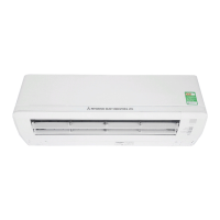
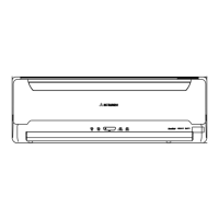
Provides detailed physical dimensions for the indoor and outdoor units.
Illustrates the refrigerant piping layout between indoor and outdoor units.
Provides charts and examples for correcting cooling capacity based on temperature and piping length.
Shows the wiring diagram and color codes for the unit.
Explains the functions and buttons of the wireless remote control.
Describes how to operate the unit using the physical ON/OFF button on the unit.
Explains the function that restores operation after a power outage.
Details steps to prevent interference when using multiple remote controls.
Explains how to control the flap and louver direction and swing.
Describes the automatic operation mode that controls fan speed and airflow direction.
Details the comfortable, sleep, and off timer functions.
Guides on setting the airflow direction based on installation position.
Explains the operation of major components during cooling.
Describes the operation logic for dehumidifying modes.
Explains how the unit automatically determines the operation mode.
Details fan speed settings for different operation modes.
Explains the function that prevents fungus growth.
Covers frost prevention, forced operation, and self-diagnosis.
Provides critical safety warnings and cautions for installation and operation.
Guides on choosing optimal locations for indoor and outdoor units.
Details the process of mounting the indoor unit installation board and the unit itself.
Instructions for stable installation of the outdoor unit.
Steps for connecting refrigerant pipes, including preparation, connection, and air purge.
How to mount the remote control switch and its battery.
Importance and procedures for proper grounding to prevent shock.
Steps for conducting a trial run and checking operation.
Guidelines for using and installing the wireless remote control.
General procedures for troubleshooting issues before replacing parts.
Procedures for evacuation and refrigerant charging.
Detailed parts breakdown and diagrams for SRK10CFV-4 and SRK13CFV-4 indoor units.
Detailed parts breakdown and diagrams for SRC10CFV-4 and SRC13CFV-4 outdoor units.
| Refrigerant | R410A |
|---|---|
| Type | Split System |
| Heating Capacity (kW) | SRK10CFV-4: 3.20 kW; SRK13CFV-4: 4.20 kW |
| Power Supply | 220-240 V, 50 Hz |
| Coefficient of Performance (COP) | SRK10CFV-4: 3.6; SRK13CFV-4: 3.4 |
| Noise Level (Outdoor Unit) | SRK10CFV-4: 50 dB; SRK13CFV-4: 50 dB |