6
Printed in Japan
Date of publication: February 1, 2019
1
Press [BANK] to select the BANK number that you want to set.
»
The BANK indicator corresponding to the selected BANK number will light.
Tips
Select a BANK number from BANK1 through 3. Tolerance values cannot be set if
BANK0 is selected.
2
Press [Fn].
»
The BANK indicator will light in amber. (Tolerance value S1 will be selected.)
Tips
Tolerance values are set in the order S1, S2, S3, S4. The Tolerance judgment
indicator displays as shown in the following table. (The tolerance value to be set
will be selected.)
Tolerance value BANK indicator
S1 Amber indicator on
S2 Amber indicator blinks
S3 Red indicator blinks
S4 Red indicator on
3
Set the tolerance values using the same procedure as for setting
the 3-step tolerance values.
»
The values will be applied in the order S1, S2, S3, S4, and then the Counter will
return to the Counter display.
Tips
• For details about setting the 3-step tolerance values, see "3-step tolerance
value setting (3-step tolerance zone selection)" (page 5).
• An error will occur unless S1 < S2 < S3 < S4 or S1 = S2 = S3 = S4.
4.5
Optional Constant Value Setting
You can set an arbitrary multiplication factor for the counter value. If this
function is used, the accuracy cannot be guaranteed.
Tips
• Set the value of parameter number 16 to 3 (arbitrary value) in advance.
• When an arbitrary constant is set, the decimal point will blink.
This section explains how to set an arbitrary multiplication factor.
1
Press and hold [Fn], and then press [P.SET].
»
The Counter enters Parameter mode.
(The set value of parameter number 00
will blink.)
Parameter number Set value
2
Press [P.SET] twice to set the value to 2.
»
The display appears as to the right.
Parameter number Set value
3
Press [Fn].
»
The previous multiplication factor will
be displayed. (The example on the right
shows the previous value as 1.0000.)
4
Press [MODE].
»
The input digit will shift to the right. (The
currently selected digit will blink.)
5
Press [P.SET].
»
The multiplication factor will be modied.
6
Repeat step
4
and step
5
until the least signicant digit has
been set.
»
The least signicant digit will blink.
Tips
The setting range is
±
9.9999.
7
Press [MODE].
»
The multiplication factor will be applied.
(The least signicant digit stops
blinking.)
8
Press and hold [Fn], and then press [P.SET].
»
The Counter will return to the Counter display.
5
External Input/Output Function
This product has an I/O connector that enables data communication with
external equipment. There are 2 types of external output modes: "Tolerance
judgment output mode", which outputs the tolerance judgment result, and "BCD
output mode", which outputs the counter data with BCD. Also, you can activate
the Preset function and activate HOLD on the counter value through external
signal input.
5.1
Connections
Compatible plug and connecting cable
Compatible plug:
y
Option No. 02ADB440 (plug and cover set)
y
Commercial plug 10136-3000PE (3M), cover 10336-52A0-008 (3M)
y
Commercial plug DX40M-36P (HIROSE), cover DX30M-36-CV (HIROSE)
Cable: Use shielded wires and limit the connecting cable length to 3 m or less.
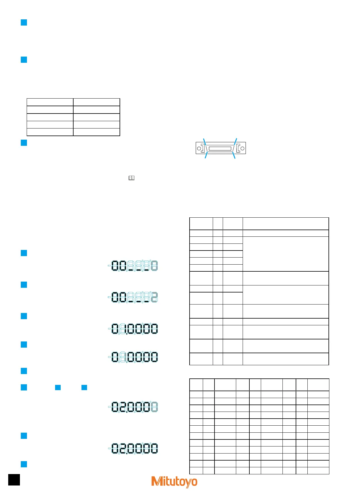
Pin assignment
Tips
• External input is valid when input voltage is "L". (External input is negative logic.)
• "I/O" in the following table refers to the rst letters of "Input/Output" respectively.
Refer to the input circuit for "I", and the output circuit for "O".
• In BCD output mode, it is possible to invert the output logic of pin numbers 3
through 26 and pin number 31 by setting parameter number 24 (BCD output logic).
z
Tolerance judgment output mode
Pin
number
I/O Name Functions
1, 2 - COM Internally connected to GND
3 O L1 Tolerance judgment result output
y
Relevant output terminal: "L"
y
Output on error: both L1 and L5 are "L"
4 O L2
5 O L3
6 O L4
7 O L5
10 O NOM Normal output
Normal: "L"
27 I SET1 Setting BANK, Peak mode:
Input the set value with SET in advance, then
assign with MODE, BANK.
28 I SET2
29 I MODE Switching Peak:
Input in combination with SET.
34 I HOLD HOLD input
35 I P.SET Normal measurement: Preset
Peak mode measurement: Peak clear
36 I BANK Switching BANK:
Input in combination with SET.
- - NC No connection should be made other than
those shown above.
z
BCD output mode
Pin
number
I/O Name
Pin
number
I/O Name
Pin
number
I/O Name
1 - COM 13 O 4
×
10
2
25 O 4
×
10
5
2 - COM 14 O 8
×
10
2
26 O 8
×
10
5
3 O 1
×
10
0
15 O 1
×
10
3
27 I SET1
4 O 2
×
10
0
16 O 2
×
10
3
28 I SET2
5 O 4
×
10
0
17 O 4
×
10
3
29 I MODE
6 O 8
×
10
0
18 O 8
×
10
3
30 - NC
7 O 1
×
10
1
19 O 1
×
10
4
31 O SGN
8 O 2
×
10
1
20 O 2
×
10
4
32 O NOM*
1
9 O 4
×
10
1
21 O 4
×
10
4
33 O READY*
2
10 O 8
×
10
1
22 O 8
×
10
4
34 I HOLD*
1
11 O 1
×
10
2
23 O 1
×
10
5
35 I PSET*
1
12 O 2
×
10
2
24 O 2
×
10
5
36 I INH*
3
1
19
18
36
 Loading...