7
Printed in Japan
Date of publication: February 1, 2019
*
1
The same function as in tolerance judgment output mode.
*
2
"L" when output data is xed.
*
3
During input, the output of pin numbers 3 through 26 and pin number 31 is "H".
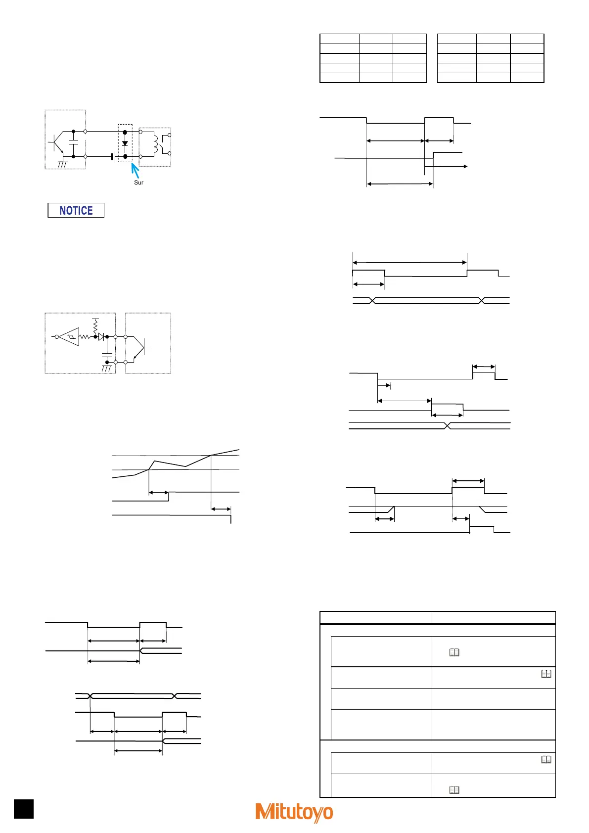
Output circuit
Transistor is on when the output is "L" (open collector).
COM
0.01 µF
Counter
TD62583 equivalent
Output
External
equipment
Reference
circuit
Output withstand voltage: Max. 24 V
Output current: Max. 10 mA
Output saturation voltage: Max. 0.7 V
Surge-current-absorbing diode
60 V 100 mA or more
• When using relays, incorporate a surge-current-absorbing diode or a protective
circuit. If no protection is incorporated, the IC in the Counter may be damaged.
• The output current when the tolerance judgment result is output is
20 mA at maximum.
Input circuit
Input is valid when the input voltage is "L".
+5 V
5 kΩ
5 kΩ
0.01 µF
Input current: Max. 1 mA
Input voltage: H = 4 to 24 V
L = Max. 1 V
Counter
External
equipment
Use open-collector
output or relay
output, etc.
Reference
circuit
5.2
Timing Chart
z
Tolerance judgment result output
Max. 10 ms
Max. 10 m
NG
-NG
Upper specication limit
Lower specication limit
Counter data
Tips
• After acquiring the counter data, there is a maximum 10 ms delay before the
tolerance judgment result is output.
• For EG-101D, the length of time until the tolerance judgment result is output
after the counter data enters in the Specication range depends on the
connected equipment, such as the Linear Gage.
z
Preset, Peak clear
Min. 10 ms
Min.
10 ms
Max. 10 ms
BCD data
z
Peak mode/BANK specication
MODE
BANK
Min. 10 ms
Min.
10 ms
Min.
5 ms
Max. 10 ms
DATA
BANK (pin number 36):
BANK switchover
MODE (pin number 29):
Peak switchover
SET2 SET1
BANK0 H H
BANK1 H L
BANK2 L H
BANK3 L L
SET2 SET1
NOMAL H H
MAX H L
MIN L H
TIR L L
z
HOLD
Error cancellation
(For EG-101Z: origin detection wait state)
Min. 10 ms
Min.
10 ms
Max. 15 ms
BCD data
Tips
During HOLD input, the UNIT indicator will blink.
z
Interval mode
Continuously outputs data using the Counter's internal timing.
*1 Depends on the setting of Parameter number 23
EADY
(T1) Min. 5/15/20/40 ms*1
(T2) Min. 2/5/8/14 ms*1
BCD data
z
Command mode
Outputs data using sync control via HOLD and READY.
EADY
HOLD
Max. 15 ms
(T2)
Data latch max. 10 µs (EG-P/Z)
BCD data
z
INH input
BCD data output is switched off during INH input.
INH
Max. 10 ms
Max. 10 ms
BCD data
6
Troubleshooting
6.1
Troubleshooting
When the Counter does not operate as expected, refer to the cause of the
trouble and the solutions shown below:
Cause Solution
Symptom 1: The counter value is incorrect (not counting).
Parameters are not correctly
set for the type of the Linear
Gage, etc.
Set correct parameters. For details,
see
"3.2 Basic Parameters" (page
3).
Peak mode (MAX or MIN is lit)
is active.
Cancel Peak mode. For details, see
"4.2 Peak Mode Setting" (page 5).
The HOLD signal (UNIT is
blinking) is being input.
Check the external input.
Calculation with a constant
function is set.
Cancel calculation with a constant
function. (Set parameter number 16 to
0.)
Symptom 2: Cannot execute Zero setting.
Peak mode is active.
Cancel Peak mode. For details, see
"4.2 Peak Mode Setting" (page 5).
The Preset value is a value
other than 0.
Set the Preset value to 0. For details,
see
"4.1 Preset" (page 4).
 Loading...