5.2.3 Make sure “LO BAT” Does not show at left upper corner of display
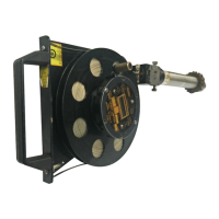
5.2.4 After grounding the assembly, insert the barrel of the gauging
into the valve. Un-lock the tape reel lock, by rotating the brass lock thumbscrew
counterclockwise turning position hub seat. Grasp the knurled reel crank hand and
lower the sensor head tape assembly, which contains the sonic sensor, into the tank.
Always exert a restraining force to prevent the sensor from descending too
rapidly or free falling.
CAUTION!
Under no circumstances should the reel and tape be permitted to unwind without
restraint. Permanent damage may be incurred to the sensor head or to the calibrated
tape if the head is permitted to fall freely.
5.2.5 Lower the sensor head slowly until a tone steady is heard. If the surface of
the fluids is oil or other non-conductive fluid, a continuous audible tone will be
heard. If the surface of fluid is water or other conductive fluid, the audible
tone heard, will be a “beeping” tone.
5.2.6 Define measurement by raising the sensor head until the sound
just ceases. Lower until sound is just heard again, to refine ullage level.
5.2.7 Place gauging tape against ullage referenced point and read ullage on tape
Note this reading as the surface liquid ullage level.
5.2.8 To find the oil-water interface point, continue to lower the sensor into fluid,
noting that the audible tone is continuous. When the audible signal changes to a
“Beeping” tone, the sensor has entered the water column underneath the oil.
5.2.9 Raise the sensor very slowly until the tone once again becomes continuous.
Repeat if necessary to refine water entry point (Interface level).
5.2.10 Again, read the ullage on the tape. By subtracting the first reading obtained
(step 7) from this reading, the total product depth is thus determined. By subtracting
the second water level ullage from the maximum tank depth, water level innage is
determined.
5.2.11 When the measurement is completed, place the spring loaded wiper knob in
the “On” position while rewinding the tape until sensor is stored with
in the vapor valve entry barrel. Do not close the vapor valve until the fully
“stowed” position is confirmed,
by noting that yellow pop-up button on top
of the wiper housing is “up”
5.2.12 Lock the reel by rotation the crank/reel lock thumbscrew down position (parallel
to hub).
Depress power “Off/On” switch to conserve battery power.
5.2.13 Close the vapor valve, disconnect the valve securing cap, remove the
gauging unit, disconnect the grounding cable. Replace the vapor valve cap.
Page 9