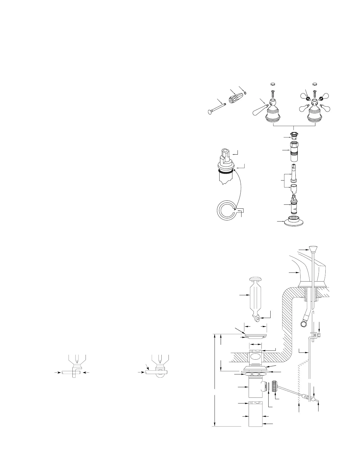
1. Thoroughly clean around drain opening in lavatory sink. Apply 1/4 inch bead of
plumber's putty (not furnished) around the bottom side of drain seat (as shown).
2. Apply pipe joint compound (not furnished) to top threaded end of the drain body.
Slip drain body up through the drain opening and screw seat onto the drain body.
3. Position the drain body (with pivot rod opening extending rearward) and tighten
mounting nut until the drain body is snug. Wipe excess plumber's putty from the
drain seat area. Apply pipe joint compound (not furnished) to top threaded end of
tailpipe and screw into drain body. Tighten firmly by hand.
4. Position drain plug in either of the following ways:
A. VANDALPROOF - This design is to prevent unauthorized removal of the drain
plug. Unscrew the pivot nut and remove the pivot rod. Inside the drain body posi-
tion the pivot rod through the drain plug hole as shown in the illustration below.
Screw the pivot nut back on the drain body. DO NOT OVERTIGHTEN.
B. EASY REMOVAL - This design is for quick removal of drain plug for cleaning.
Just drop in the drain plug as shown in the illustration below.
5. Install lift rod, with knob attached, into top of spout as shown. Secure lift rod strap
to bottom end of lift rod as shown. With pivot rod in the down position, assemble
strap to pivot rod using the spring clip. The strap will have to be bent to reach the
pivot rod on some installations. Adjustment may be required so lift rod clears
spout tube and connection.
6. With the drain plug in full open position, adjust lift rod and knob to clear faucet and
tighten lift rod strap screw.
LIFT ROD
AND KNOB
SPOUT
VANDAL-
PROOF
HOLE
DRAIN
PLUG
2-1/8"
LIFT
ROD
STRAP
SCREW
LIFT
ROD
STRAP
1-1/2"
PIPE
JOINT
COMPOUND
OR
TAPE
TAPE (NOT
FURNISHED)
SEAT
MAX. 2-1/2"
MIN. 1-1/2"
8"
MOUNTING
NUT
DRAIN
BODY
PIPE
JOINT
COMPOUND
OR
TAPE
TAPE (NOT
FURNISHED)
1-1/4"
TAILPIECE
PIVOT
ROD SEAT
PIVOT
NUT
LIFT ROD
STRAP
SHOWN
IN BENT
POSITION
PIVOT
ROD
SPRING
CLIP
BOTTOM
GASKET
FLAT
WASHER
Disassembly
Reassembly
TO INSTALL HANDLE INSERTS
1. Be sure o-ring is in place on
insert at shown.
2. Screw insert(s) into handle hub.
Lavatory Lift Rod and Waste Assembly
CAUTION: Failure to follow these instructions can cause personal injury
or water damage to the premises, or could result in a faulty installation
or damage the new cartridge.
1. Assemble upper and lower handle adapter and the handle hub to new cartridge
with the handle screw. Turn stem to the ON position, waterway holes in cartridge
are lined up.
2. Insert the cartridge straight into the valve body, press firmly while rotating the han-
dle hub counterclockwise until you feel the key enter notch in the valve body. This
will correctly position the cartridge. Turn handle knob in both directions to insure a
stop in each direction.
3. Note handle rotation and orientation if adjustment is required (see Installation
Instruction #6 on previous page).
4. Remove handle screw and handle hub, install cartridge nut with stem guide over
the upper handle adapter, start by hand DO NOT CROSS THREAD. Firmly tighten
cartridge nut and stem guide using adjustable wrench.
5. Replace handle parts (follow illustration on previous page). Turn on water supplies.
CAUTION: Turn OFF BOTH water supplies and open BOTH faucet han-
dles to relieve water pressure to insure that COMPLETE water shut-off
has been accomplished.
1. Remove plug button, handle screw and handle hub.
2. Loosen the cartridge ntu with an adjustable wrench and remove it and the stem guide
as a unit together with the upper handle adapter.
3. Set aside the cartridge nut and stem guide and with the handle adapter installed,
reassemble handle hub and handle screw and tighten.
4. Grasp the handle hub and pull the cartridge STRAIGHT UP and out of the valve body.
A. VANDALPROOF
PIVOT
ROD
VANDALPROOF
POSITION
B. EASY REMOVAL
POSITION FOR
EASY REMOVAL
PIVOT
ROD
O-RING
O-RING
O-RING
ACRYLIC
HANDLE
INSERT
BOLT
STEM
KEY
NOTCH
IN
BODY
CARTRIDGE
NUT
STEM
GUIDE
STEM
EXTENSION
CARTRIDGE
ESCUTCHEON
 Loading...