®
Melt-Cube
Not under documentation control if printed. May be revised without notice. ©05-2014
Electronic version is available at www.moldmasters.com
Hot Runner User Manual Revision 18
15-5
Optional Quick Disconnect Terminal
Ends
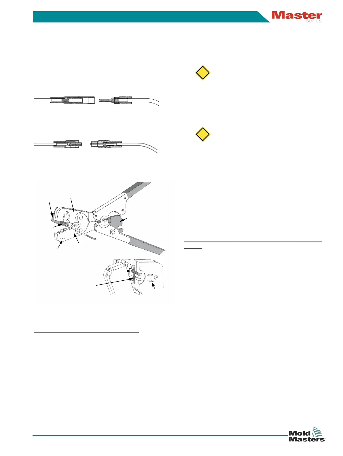
Optional quick disconnect terminal end kits are avail-
able on request. The kit consists of:
• QDISC-CRIMP Tool
• TERMCON09 (Power)
• TERMCON10 (Thermocouple)
Figure 15-9: Power Quick Disconnect Terminal Ends
Figure 15-10: Thermocouple Quick Disconnect
Terminal Ends
Crimping the Quick Disconnects
Select the appropriate loose-piece contact and identify
the crimp cavity according to the wire size markings
on the tool.
1. Hold tool so wire side is facing you. Make sure
ratchet is released. Squeeze tool handles together
and allow them to open fully.
2. Grasp locator and simultaneously move locator to-
ward anvil jaws and push locator slide into crimper
jaws. Spring tension will hold locator position
against crimper jaws.
Locator
Back of
Tool
Anvil
Jaws
Crimper
Jaws
Ratchet
Disengaged
Wire Stop
Wire Size
Markings
Wire Stop
Slot (In Contact)
Assembling the System with Quick Discon-
nects
1. When assembling the system, connect female and
male connector pins.
2. Then screw male sleeve into female sleeve.
Figure 15-11: QDISC-CRIMP Tool
3. Insert contact mating end into appropriate hole in
locator slide. Orient contact so wire barrel and in-
sulation barrel are facing crimper jaws (wire size
markings).
CAUTION
Do not attempt to close tool handles when
locator slide is positioned between crimp-
ing jaws - damage to the tool jaws and/or
locator slide may result.
4. Pull locator slide out of crimping jaws. Spring ten-
sion will pull locator down and allow wire stop to
enter the slot between barrel and contact shoulder.
CAUTION
Make sure both sides of the insulation bar-
rel are started evenly into the crimper jaws
- do not attempt to crimp an improperly
positioned contact.
5. Squeeze tool handles together until ratchet engag-
es. Do not deform insulation barrel or wire barrel.
6. Insert properly stripped wire contact into the wire
barrel until wire butts against the wire stop.
7. Holding wire in place, squeeze tool handles togeth-
er until ratchet releases. Allow tool handles to open
fully. Move locator toward anvil jaws and remove
crimped contact.
CAUTION
CAUTION


 To Next Page