EasyManua.ls Logo

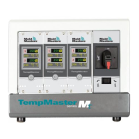
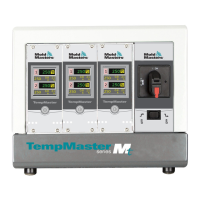
Mold-Masters TempMaster MT-06-06 User Manual

Default Icon
100 pages
To Next Page IconTo Next Page
Page #1 background imageLoading...
Page #1 background image
version 4
Original Instrucons
User Manual

Table of Contents

Questions and Answers:

Mold-Masters TempMaster MT-06-06 Specifications

General IconGeneral
Control TypePID
Number of Zones6
Input TypeThermocouple (J, K, T)
DisplayLCD
CommunicationRS-485 (Modbus RTU)
ModelTempMaster MT-06-06

Summary

Section 3 - Safety

3.1 Introduction

Emphasizes user responsibility for safety and compliance with standards.

3.2 Safety Hazards

Identifies common safety hazards in injection molding equipment.

3.3 Operational Hazards

Details potential hazards during equipment operation.

3.4 General Safety Symbols

Explains common safety symbols and their meanings.

3.5 Wiring Check

Provides guidelines for checking system mains and controller to mold wiring.

3.6 Lockout Safety

Details procedures for ensuring safety during maintenance using lockout/tagout.

3.7 Electrical Lockout

Explains the process of electrical lockout/tagout procedures.

3.7.1 Energy Forms and Lockout Guidelines

Lists energy forms, sources, and corresponding lockout guidelines.

3.9 MT/MT2 Controller User Hazards

Highlights specific electrical shock and environmental hazards for MT controllers.

Section 4 - Overview

4.1 Specification

Lists general specifications for the MT controller.

4.3 Tool Connections

Refers to wiring details for connecting the controller to the tool.

4.7.1 Controller Modules

Details the components of a controller module: thermocouple inputs, CPU, and output triacs.

4.8 How the MT Controller Works

Explains the closed-loop operation of MT controllers.

Section 5 - Setup

5.4 Change Zone PID Characteristics

Details how to adjust PID settings for zone response time.

5.8 Monitor Temperature Limits

Describes setting deviation limits for Over and Under Temperature alarms.

5.8.1 Warning and Alarm Limits

Details how warning and alarm limits function.

5.9 Set Ground Fault Detection

Explains how to enable or disable ground fault detection.

5.10 Set Mold Leak Detection

Describes the leak detection function and its alarm signaling.

5.11 Set Response to Thermocouple Failure

Configures the controller's response to a thermocouple failure.

5.12 Restrict Access to Manual, Standby or Boost

Details how to restrict user access to certain functions via password.

5.13 Extend Alarms for Manual, Standby or Boost Operation

Configures external alarm outputs for Manual, Standby, or Boost modes.

Section 6 - Operation

Section 7 - Maintenance

7.2 Restore Factory Settings and Recalibration

Explains how to restore default settings and perform calibration.

7.2.2 Calibration Routine

Outlines requirements for temperature calibration.

7.2.3 Calibration Sequence

Provides step-by-step instructions for the calibration sequence.

7.2.4 M.Dis Option

Explains how to enable or disable user options like Manual, Standby, or Boost.

7.3 Fuses and Overcurrent Protection

Details fuses and overcurrent protection for the controller.

Section 8 - Troubleshooting

8.1 Individual Card Diagnostics

Describes features for diagnosing faults in cards, heaters, and sensors.

8.2 Other Possible Fault Conditions

Covers rapid temperature fluctuations and ground fault detection.

8.2.1 Rapid Temperature Fluctuations

Explains causes of temperature fluctuations and testing earth connections.

8.2.2 Ground Fault Detection

Details ground fault detection and troubleshooting earth faults.

Section 9 - Wiring Details

Related product manuals