Section 3
GENERAL INFORMATION
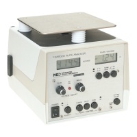
The Charged Plate Analyzer Model 268A separates into two components connected by
a ten-foot cable. The top part with the plate attached contains the fieldmeter portion of
the instrument and may be placed at the measurement site. The bottom part with the
controls and indicators may be placed in a convenient operating location remote from
the detector. To separate the two components, release the two over-center latches near
the rear of the unit and lift up at the rear of the top section.
A 1/4-20-threaded receptacle is provided inside of the top section for convenient tripod
mounting.
Two foldout legs are provided underneath the bottom of the control unit to elevate the
front of the cabinet to permit easy viewing of the meters.
Switches on the front panel are alternate action push-push type with the exception of the
three used for "plate control". These are mechanically interlocked so that only one
function can be selected at a time.
Controls are grouped by function.
The three pushbutton switches directly beneath the "PLATE VOLTAGE" meter relate to
meter range and function.
The three switches at the lower center of the panel labeled "PLATE CONTROL" affect
the charge/discharge condition of the plate.
The "HV" control knobs, the "HV ON" indicator and the "POLARITY" pushbutton switch
relate to the polarity and magnitude of the initial charge voltage on the plate.
The "TIMER LIMIT" switch sets the start/stop voltage limits for the timer.
The "OUTPUT" BNC connector (on the back panel) allows an oscilloscope or recorder
to be connected to the output of the fieldmeter. The signal here is 1/1000th of the actual
voltage on the plate—regardless of the settings of the meter range and function
switches.
Two small holes are provided in the plate for the attachment of standard or miniature
banana plugs, useful for measuring induced charge or decay rate on personnel.