 Need help?
Do you have a question about the Montalvo X-3000-ce-RW and is the answer not in the manual?
Explains how load cells measure total web tension via Wheatstone bridge.
Explains how motors/clutches convert electrical signals to torque to change web tension.
Controller uses feedback to maintain set tension automatically.
Operator manually sets output torque; no automatic regulation.
Details electrical specifications: AC input, fuse size, power consumption, noise immunity.
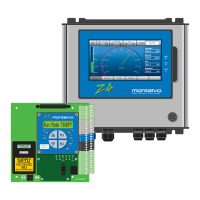
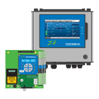
Provides mechanical specifications: dimensions and weight for both versions.
Guidelines for mounting in dry, vibration-free locations, away from EMI sources.
Emphasizes professional installation, codes, voltage selector, fuse, and shielded cable use.
Lists input terminals for extra outputs, analog outputs, external gain, and summation input.
Lists output terminals for extra outputs, diameter/trim input, and diameter output.
Details terminals for load cell input (-2.5V, +INPUT, +2.5V) and related connections.
Describes connections for the main power supply: L, N, and PE terminals.
Explains connections for regulated voltage and current outputs for meters or drives.
Details wiring for direct load cell connections, including voltage supplies and input signals.
Connects to CCW terminals of splice level potentiometer.
Input for external signal to set output during splice mode (0-10V).
Activates output switching for new roll during flying splice, timing set by SPLICE menu.
Connects to CCW terminal of MANUAL potentiometer.
0-10V input for manual or soft start modes, connected to MANUAL potentiometer wiper.
Connects to CCW terminals of the diameter potentiometer.
Input for diameter reference (0-10V) from sensors or calculators.
Visual representation of input/output connections for the X-3000-ce-RW controller.
Lists diagnostic parameters and their status (No/Yes).
Information on passwords required for SETUP and ENGINEERING menus.
Outlines engineering menu options like PID menu for P and D levels.
Lists diagnostic parameters: version, tension, dancer, and setpoint.
Covers status parameters: softstart, anticOast, splice, inertia, and run mode.
Details setup menus: mode, language, gain, ratio, and softs.
Lists engineering parameters: PID, inertia, splice, webbr, and diameter menus.
Outlines setup options for load cell rewind mode: mode, language, and gain.
Describes inertia setup functions: static and dynamic friction compensation.
Details splice setup functions: source, delay, level, and time.
Covers web break setup functions: level and time.
Defines diameter source options: internal, pulses, or analog input.
Specifies pulses per roll revolution for diameter calculation.
Defines mm between pulses for diameter calculation.
Explains correction factor for diameter calculation and its adjustment.
Sets the minimum diameter in % or mm.
Sets the maximum diameter in % or mm.
Specifies number of pulses from roll for diameter calculation.
Details mechanical installation specifics for the 'P' version of the controller.
Adjusts tension display to zero (tare).
Adjusts tension display for actual web tension.
Adjusts tension display for high scale calibration.
Adjusts diameter screen to zero.
Adjusts diameter screen for actual diameter.
Calibrates summation input level.
Ensure load cells are mounted and oriented correctly.
Mechanically zero the tension meter before applying power.
Apply power and let the controller warm up for at least 10 minutes.
Adjust R1 until tension meter reads zero with no web tension.
Thread rope, attach known weight (>=25% full scale) for calibration.
Adjust R2 until tension meter matches weight and shows correct % of full load.
Remove weight and check if tension meter returns to zero. Repeat if necessary.
Reduces web tension as roll diameter increases to prevent telescoping/starring.
Defined by R4/R5, this is the active range for the taper function.
Amount of setpoint reduction due to taper function, ratio of tension at Dmax to Dmin.
Input signal (-10 to 10V) proportional to roll diameter from sensors or calculated.
Set the operating mode to X-RW for tuning.
Adjust tension as described in section 4.2.
Ensure correct diameter calculation via DIAM.MENU, important for taper.
Adjust static/dynamic friction in INERT MENU for correct rewinder function.
Adjust GAIN, inertia, and RATIO at low speed with running machine.
Setting for Taper % and Splice Level on the front panel.
Setting for Taper % and Splice Level on the front panel.
Setting for Taper % and Splice Level on the front panel.
Setting for Taper % and Splice Level on the front panel.
Setting for Taper % and Splice Level on the front panel.
Setting for Taper % and Splice Level on the front panel.
Displays actual web tension from 0-100%.
Displays regulated output from 0-100%, used for clutch friction adjustment.
Selects between automatic (closed loop) and manual (open loop) operation modes.
Turns the regulator output on or off.
Sets output in MANUAL mode; requires constant manual adjustments.
Sets desired tension in AUTO mode; controller adjusts output automatically.
Lists common symptoms like unstable tension in manual/auto modes.
Identifies potential causes for symptoms: mechanical, pneumatic, or regulator issues.
Provides checks for symptoms: tuning, terminal points, or load cells.
 General
| Type | Tension Controller |
|---|---|
| Model | X-3000-ce-RW |
| Manufacturer | Montalvo |
| Output | 0-10 VDC, 4-20 mA |
| Display | LCD |
| Input Voltage | 24 VDC |
| Output Current | 4-20 mA |
| Operating Temperature | -10°C to 50°C |

 To Next Page