Do you have a question about the Montalvo Z4-UD and is the answer not in the manual?
Provides a general introduction to the Montalvo Z4 Unwind controller and its function.
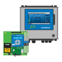
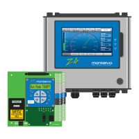
Details available Z4 controller models, optional features, and compatibility with older units.
Explains the operational principles and system integration of the Z4 controller.
Describes the controller's primary functions and typical operating modes.
Provides dimensional drawings for the Z4 controller circuit board for installation planning.
Details the physical dimensions of the remote HMI interface for panel mounting.
Shows the external dimensions of the Z4 controller's industrial enclosure.
Covers essential safety precautions, electrical hazards, and EMC requirements for installation.
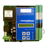
Illustrates the wiring and connections for the Z4b circuit board only model.
Shows wiring diagrams for the Z4r model with a remote HMI.
Details electrical connections for the Z4e model with HMI in an enclosure.
Provides a comprehensive list and description of all controller terminal connections.
Explains the wiring and setup for connecting dancer position sensors (DPS-1, MDP-6).
Guides the user through zeroing and calibrating the DPS-1 dancer sensor.
Guides the user through zeroing and calibrating the MDP-6 dancer potentiometer.
Details how to configure and connect regulated voltage or current outputs.
Explains the correct wiring for both AC and DC power supply connections.
Describes the function and wiring of the Z4's 24V digital input terminals.
Explains the configuration and use of the Z4's 24V digital output terminals.
Covers the setup and use of analog inputs for external signals like diameter.
Describes the controller's analog output capabilities for proportional signals.
Details the specific configuration and purpose of the Aux1 analog output.
Explains the function and setup of the internal voltage-to-current converter.
Provides essential steps and guidelines for tuning the Z4 controller's PID parameters.
Explains the initial setup options for controller type, amplifier gain, and saving configurations.
Details how to enable or disable optional functions to customize controller behavior.
Describes PID parameters like Gain, Integral Time, and Derivative Level for system tuning.
Covers parameter settings for managing roll changes, including new output levels.
Explains how to properly start the machine and set initial output levels.
Details methods to prevent tension drop during machine stops using fast stop signals.
Explains the hold function for maintaining output during stopped conditions.
Covers setting up diameter reference sources for control and system functions.
Describes the taper function, used to adjust tension as roll diameter changes.
Explains how to configure digital outputs for alarms like web break or diameter.
Details the controller's sequence for managing web splices and output adjustments.
Explains the range expander for managing multiple braking torque levels effectively.
Covers the setup and use of the first auxiliary analog input for external signals.
Details the configuration and application of the second auxiliary analog input.
Explains the setup and parameters for the Aux1 analog output.
Describes the configuration and purpose of the Aux2 analog output.
Explains navigation and interaction with the controller's menu system.
Details the structure of the status menu and its displayed parameters.
Defines the different run modes (AUTO, MANUAL, START, STOP, HOLD) of the controller.
Outlines the structure of the setup menu for accessing configuration parameters.
Provides a detailed listing of all configurable parameters and their ranges.
Describes the function and meaning of the various LEDs on the controller and HMI.
Explains the location and function of the potentiometers for hardware adjustments.
Presents a system block diagram for understanding controller interconnections and signals.
Lists common operational symptoms and their potential causes and checks.
Provides detailed technical specifications for the Z4 controller's electrical and environmental properties.
Details the product's compliance with relevant Low Voltage and EMC directives.
Explains the setup and functionality of the optional Human Machine Interface (HMI).
Describes the setup and capabilities of the optional Ethernet communication module.
| Brand | Montalvo |
|---|---|
| Model | Z4-UD |
| Category | Controller |
| Language | English |