Potential Trouble
Servovalve does not follow input command
signal. (Actuator or components are
stationary or creeping slowly).
High threshold. (Jerky, possible oscillatory
or "hunting" motion in closed loop system).
Poor response. (Servovalve output lags
electrical command signal).
High Null Bias, (High input current required
to maintain hydraulic cylinder or motor
stationary).
Probable Cause
1. Plugged inlet filter element.
1. Plugged filter element.
1. Partially plugged filter element.
1. Incorrect null adjustment.
2. Partially plugged filter element.
Remedy
1. Replace filter element.
1. Replace filter element.
1. Replace filter element.
Check for dirty hydraulic fluid in system.
1. Readjust null.
2. Replace filter element and check for dirty
hydraulic fluid in system.
7.TROUBLESHOOTING CHART
The following troubleshooting chart list potential troubles encountered, probable causes, and remedies.
8. FILTER ASSEMBLY REPLACEMENT
a. Remove eight socket head cap screws and lockwashers using a
5
/
32
inch
Allen wrench. Remove end caps.
b. Remove O-Rings from end caps.
c. Remove filter plug and inlet orifice assembly from both sides of body.
Note: 2-56 screw threads into the filter plug and inlet orifice assembly.
Remove filter.The inlet orifice assemblies are matched to each other and
are therefore interchangeable.
Note: These assemblies seat in body and cannot go through bore during
removal.
d. Remove O-Rings from filter plugs and O-Rings from inlet orifice
assemblies.
e. Visually inspect filter orifice assemblies for damage or foreign matter.
f. Discard O-Rings and filters.
g. Install O-Rings on filter plugs, and O-Rings on inlet orifices.
h. Install filter, inlet orifice assembly, and a filter plug in body. Inlet
orifice assembly pilots into filter. Install the other inlet orifice assembly and
filter plug into other end of filter. Inlet orifice assemblies are
interchangeable.
i. Install O-Rings on end caps.
j. Install end caps on body and install eight socket head cap screws and
lockwashers.Torque the screws to 57 inch-pounds.
9. FUNCTIONAL CHECKOUT AND CENTERING
a. Install servovalve on hydraulic system or test fixture, but do not connect
electrical lead.
b. Apply required system pressure to servovalve and visually examine for
evidence of external leakage. If leakage is present and cannot be rectified
by replacing O-Rings, remove the discrepant component and return for
repair or replacement.
Note: If the system components are drifting or hardover, adjust
the mechanical null of the servovalve.
c. Connect electrical lead to servovalve and check phasing in accordance
with system requirements.
10. AUTHORIZED REPAIR FACILITIES
Moog does not authorize any facilities other than Moog or Moog subsidiaries to
repair its servovalves. It is recommended you contact Moog at (716) 652-2000
to locate your closest Moog repair facility. Repair by an independent
(unauthorized) repair house will result in voiding the Moog warranty and could
lead to performance degradation or safety problems.
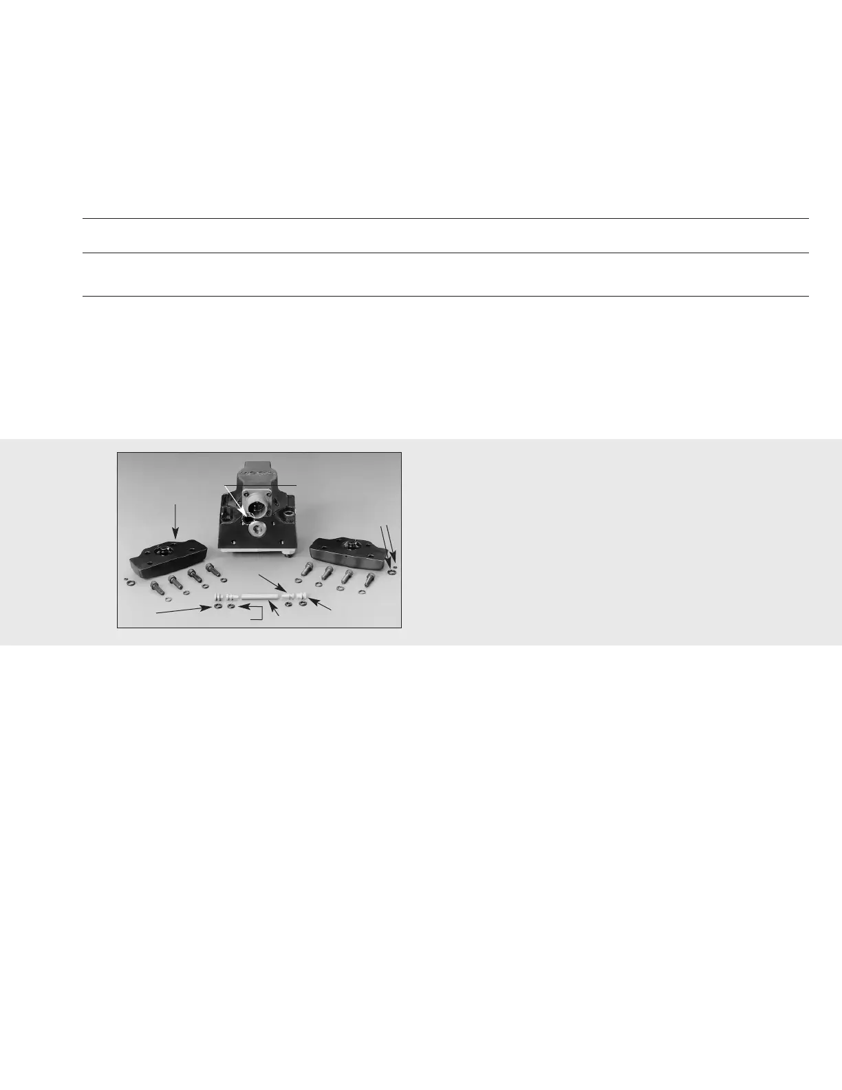
Figure 3
Inlet Orifice Assemblies
(one each end of body)
End Plate
Filter Tube
Orifice Assembly
End Cap-Body
O-Rings
Filter Plug
Filter Plug
O-Ring
Inlet Orifice O-Ring
 Loading...