22
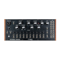
The core of Spectravox is its filter bank: a lowpass filter (filter 1), highpass filter (filter 10), and eight
bandpass filters spaced equally between (filters 2-9). In fact, Spectravox contains two filter banks: one
which analyzes the PROGRAM signal (the analysis filter bank) and one which filters the CARRIER signal
(the synthesis filter bank). When SPECTRAL SHIFT is set to zero (i.e., 12 o’clock on the panel control)
the 10 analysis filter bands and synthesis filter bands are all aligned.
1 LEVEL (2 LEVEL, etc.) (Filter level controls are indicated on panel by their number.)
Each filter in the synthesis filter bank has a control for its level—attenuating the amplitude of that
particular frequency band. With this control all the way down, that particular frequency band will be
filtered out of the CARRIER signal. In FILTER BANK mode each is a level control, while in VOCODER
mode each is an attenuator for its paired ENV F. All 10 filters are mixed at their relative levels and sent
downstream to the VCA.
The center frequencies for the bandpass filters (and cuto frequencies for the lowpass and highpass
filter, respectively) are based on Homer Dudley’s original work on the Vocoder and Voder in 1939 and
are listed below. They are the center/cuto frequencies for the synthesis filter bank when SPECTRAL
SHIFT is set to 12 o’clock (and is not being modulated) and they are the center/cuto frequencies for
the analysis filter bank at all times.
FREQUENCY:
230 Hz
320 Hz
560 Hz
830 Hz
1200 Hz
1700 Hz
2300 Hz
3200 Hz
4500 Hz
5400 Hz
TYPE:
Lowpass
Bandpass
Bandpass
Bandpass
Bandpass
Bandpass
Bandpass
Bandpass
Bandpass
Highpass
FILTER:
1
2
3
4
5
6
7
8
9
10
PANEL CONTROLS & FUNCTIONS
FILTER BANDS
BAND INPUTS:
1 VCA CV
2 VCA CV
3 VCA CV
4 VCA CV
5 VCA CV
6 VCA CV
7 VCA CV
8 VCA CV
9 VCA CV
10 VCA CV
BAND OUTPUTS:
1 ENV F
2 ENV F
3 ENV F
4 ENV F
5 ENV F
6 ENV F
7 ENV F
8 ENV F
9 ENV F
10 ENV F