32
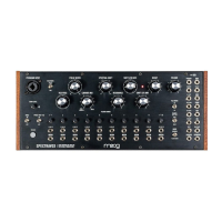
ROW SEVEN
SHIFT INPUT
This CV input for SPECTRAL SHIFT is used to jointly move the synthesis filters
up and down the frequency spectrum. A positive signal input here increases
the center frequencies of the filters and is summed with panel setting of
SPECTRAL SHIFT and SHIFT LFO settings.
CV INPUT: -5V to +5V
HOLD GATE INPUT
A gate high (approx. +2.5V threshold) in this input engages the sample and
hold circuits on all 10 analysis filter bank envelope followers—holding them at
their current levels until the gate goes low.
CV INPUT: 0V to +10V
ROW EIGHT
PROGRAM OUTPUT
This is the Audio output of the PROGRAM signal post amplification via GAIN
LEVEL knob.
AUDIO OUTPUT: -5V to +5V
PROG ENV F OUTPUT
This is the CV output for the PROGRAM envelope follower. The envelope
filter follower outputs a CV proportional to the amplitude of the full spectrum
PROGRAM signal (after amplification via GAIN LEVEL). The PROG TRIG is
generated from the PROG ENV F output.
CV INPUT: 0V to +8V
THE PATCH BAY (Continued)
SHIFT
PROGRAM
HOLD GATE
PROG ENV F