G. THE 921 VOLTAGE CONTROLLED OSCILLATOR
When the COARSE RANGE switch is in the AUDIO position, the 921 VOLTAGE CON-
TROLLED OSCILLATOR is similar in operation to one 921A OSCILLATOR DRIVER and
one 921B OSCILLATOR. The audio waveform out jacks are in the bottom row.
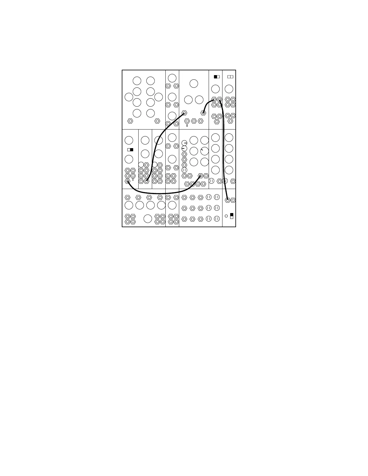
995 904A 902 902
921A 921B 923 921 911 911921B
MIXER REV CONTROLLERS TRUNK
907A
0
50
6
6
2
8’
0 0 8’
0
~
4
1. Clear the instrument of patchcords.
2. Run a patchcord from the 921 VOLTAGE CONTROLLED OSCILLATOR RECTANGU-
LAR jack to TRUNK LINE 1. The 921 generates four waveforms as does the 921B OSCIL-
LATOR. Now listen to each of the other waveforms. Vary the FREQUENCY and RANGE
controls and the SCALE switch. Note the similarity between this module and the combined
921A and 921B modules.
3. Remove the plug from the waveform output jack to the output located in the AUXILIARY
OUTPUT section of the oscillator. Move the WAVEFORM selector switch through its posi-
tions. Vary the LEVEL control. The two outputs of this section are waveforms of variable
levels. The "-" output presents an inversion of the wave just as the REVERSIBLE ATTENU-
ATOR does when in the "-" position.
When the COARSE RANGE switch is in the SUB-AUDIO position, the 921 VOLTAGE
CONTROLLED OSCILLATOR has a much lower frequency range, most of which is below
the audio spectrum. Sub-audio waveforms are most useful as control signals. For instance, if
a repetitive "siren" is desired, an audio waveform from a 921B may be made to rise and fall
in pitch either manually, by turning the FREQUENCY control back and forth, or electroni-
cally, by applying a sub-audio sine wave to the 921A FREQUENCY control input.
4. Clear the instrument and then arrange patchcords and controls as the diagram indicates. An
audio signal from the 921B should be heard.
5 . Turn the 921 AUX. OUT. LEVEL gradually clockwise. The pitch of the 921B waveform
should rise and fall according to the frequency and amplitude of the 921 controlling