H. THE 921 VOLTAGE CONTROLLED OSCILLATOR CLAMPING
POINT
The CLAMPING POINT section of the 921 VOLTAGE CONTROLLED OSCILLATOR al-
lows the waveform to be brought abruptly, or "clamped", to a manually selected point in its
cycle at the onset of a trigger signal.
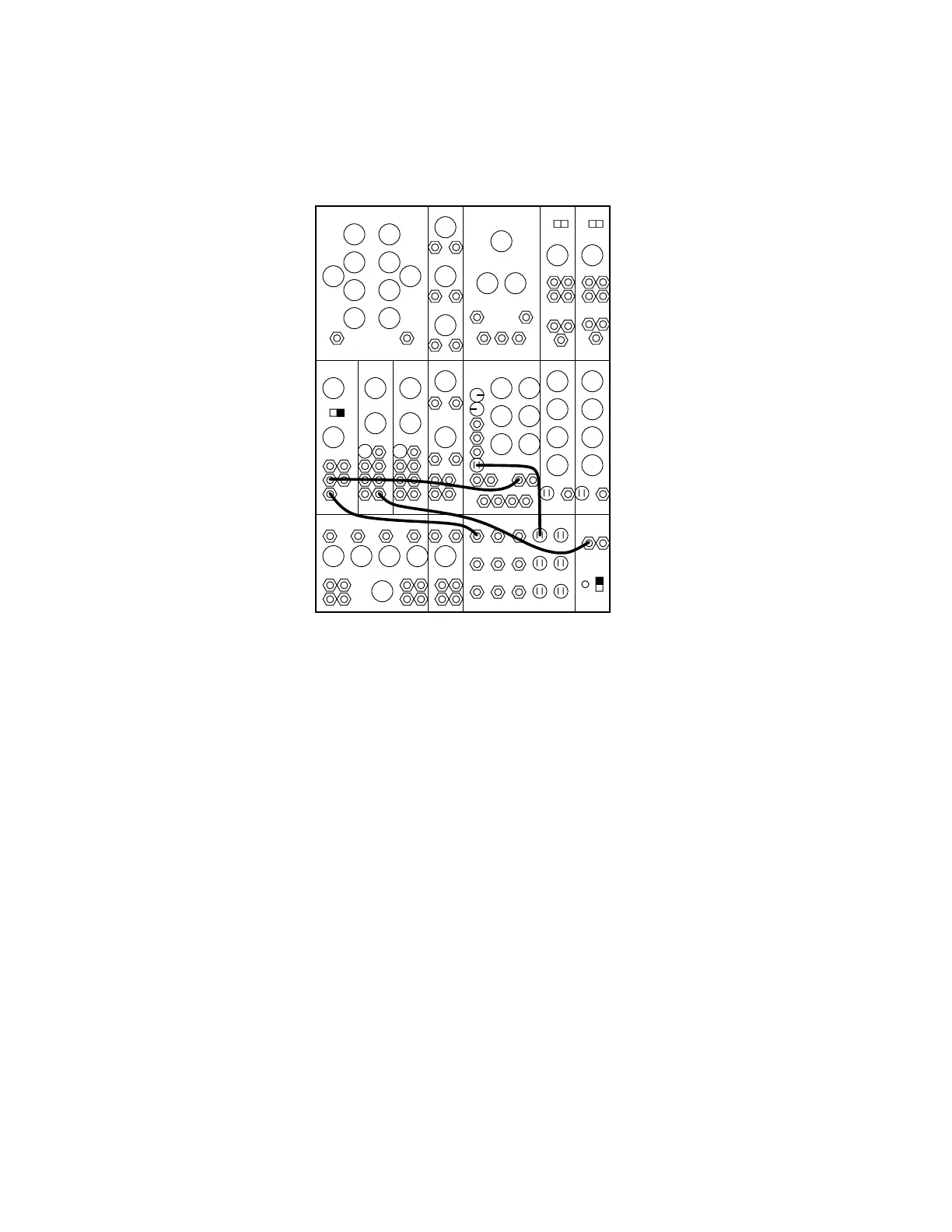
995 904A 902 902
921A 921B 923 921 911 911921B
MIXER REV CONTROLLERS TRUNK
907A
0
50
8’
0 0 8’
50
R
10
1. Arrange the controls and patchcords as indicated.
2. A sub-audio sawtooth wave is controlling the frequency of the 921B waveform. Set the
CLAMPING POINT on 50 and strike keys at random time intervals. With each new trigger
the ramp will begin at the point designated by the CLAMPING POINT control. Experiment
with various clamping point settings and all controlling waveforms.
3. Remove the trigger cable and note that the CLAMPING POINT control has no effect on
the waveforms now.