12 | Dresser
Standby Monitor
NOTE: This procedure is based on the 1st Regulator
being the operating regulator and the 2nd regulator
being the monitor regulator.
1. Set operating pilot (#1) spring at the MAXIMUM setting.
2. Set monitor pilot (#2) spring to the MINIMUM (zero)
setting.
3. Slowly open inlet block valve. Purge, if necessary, any
pressure in the station. Full inlet pressure should be pres-
ent at the Monitor Regulator and the Monitor Regulator
should be closed.
4. Open vent or downstream block valve.
5. Increase the pilot spring setting of the Monitor Regulator
until the desired monitor override setting is reached. Lock
in pilot setting.
6. With some flow going through the station, start o lower
the operating pilot setting of the Operating Regulator until
the desired outlet pressure is achieved.
NOTE: When the set point of the Operating Regulator
becomes less than the set point of the Monitor regula-
tor, the interstage pressure will drop from approximately
full inlet pressure to 5-10 PSI above the outlet pressure
at low flow rates.
Checking Standby Monitor Operation
1. With flow going through the station, slowly increase the
setting of the Operating Regulator. When the pressure
reaches the setpoint of the Monitor Regulator, the monitor
should take control and the interstage pressure should
increase to almost full inlet pressure.
2. Reduce the setting of the Operating Regulator back to
the required outlet pressure. The interstage pressure
should drop to 5-10 PSI above the outlet pressure as the
Operating Regulator takes control.
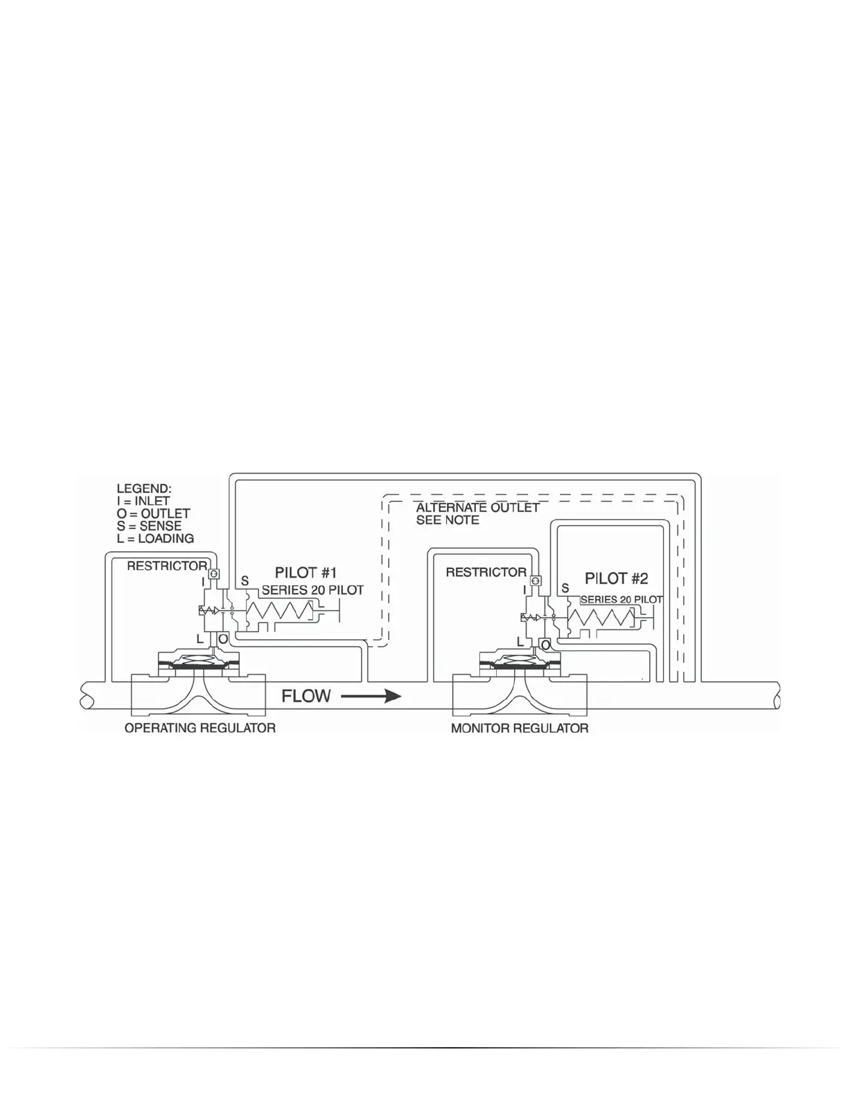
NOTE: When the differential across the entire station
(P1-P2) is less than 60 PSIG then pipe alternate outlet
as shown above. This applies to the Series 20 Pilot only;
consult with Mooney for applicability to other manufac-
turer’s pilots.
Figure 9. Standby Monitor Schematic