MOONEY INTERNATIONAL CORPORATION
M20V SERVICE AND MAINTENANCE MANUAL
Page
Date
9
Rev Date
MAR 2017
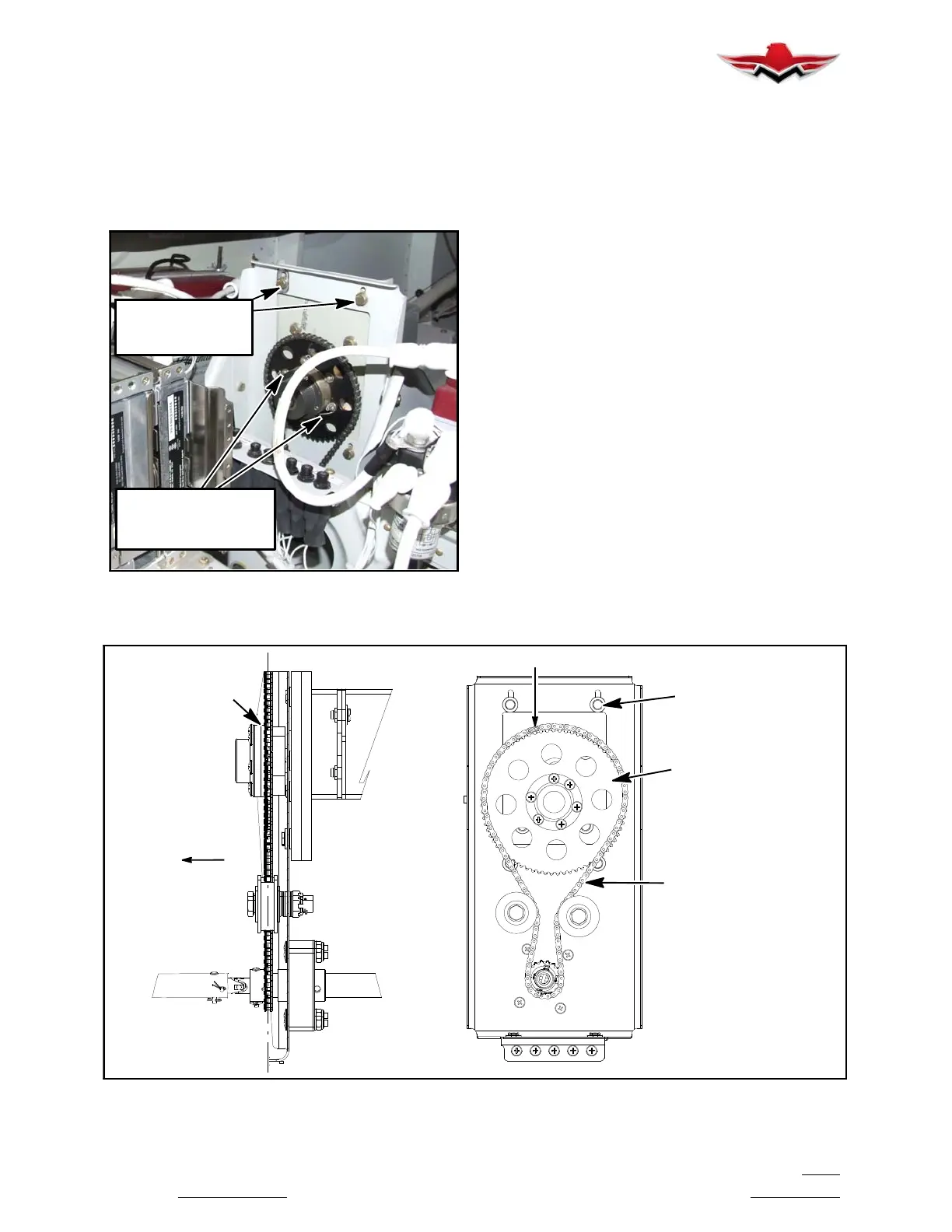
mount. A master link on the chain will allow chain to
be removed from Aircraft
. (see Figure 22- 5)
B. Cut and remove safety wire and (6) mounting
screws from end cap to remove sprocket
.
C.
Remove Servo Mount (4) attaching bolts and
remove from Aircraft.
MOUNTING BOLTS
TO ALLOW CHAIN
ADJUSTMENT
AND SPROCKET
MOUNTING SCREWS,
SAFETY WIRE,
PITCH TRIM SERVO MOUNTING
FIGURE 22- 5
3. Pitch Trim Servo Mount Clutch Adjustment
A.
For instructions on checking the slip- clutch,
refer to the GSM Slip- Clutch Setting Procedure in
the GSA 8X/GSM 86 Installation Manual (Garmin
part number 190- 00303- 83 or later revision). To de-
termine the slipclutch torque setting refer to Figure
22- 9. If a slip clutch is found to be out of spec, it
should be replaced with a new slip clutch. GSM 86
slip clutches are not settable once manufactured.
4. Installation of Pitch Trim Servo and Servo
Mount
A.
Install Pitch Trim servo mount to bracket with
original (4) bolts. Refer Figure 22- 9 Torque Chart for
Specifications (Clutch Kit 011-02147-16).
B. Use a brush or applicator, apply a thin coat of
grease to the servo output gear. Use Aeroshell
33MS or Aeroshell 17. Clean and apply grease to
output gear every 1000 hours or 3 years.
C. Install Pitch Trim servo to servo mount with
original (2) bolts. Refer Figure 22- 9 Torque Chart for
Specifications.
D. Install sprocket, dust cap assembly and se-
cure with original (6) attaching screws. Check for
alignment (top and bottom) sprockets. (see Figure
22- 6)
E. Install Safety wire (P/N MS20995-C) through
attaching screws, refer to AC 43.13- 1B CH 7 Sec-
tion 7.
F. Route chain and install master link, align so
there is no binding against sprocket and chain.
SPROCKET
ROLLER CHAIN
MASTER LINK
MOUNTING BOLTS
TO ALLOW CHAIN
ADJUSTMENT
ALIGN
SPROCKETS
AND CHAIN
LOOKING AFT
LH SIDE VIEW
FORWARD
FRONT VIEW
PITCH TRIM SERVO MOUNTING COMPONENTS
FIGURE 22- 6
22-10-02
 Loading...


