MOONEY INTERNATIONAL CORPORATION
M20V SERVICE AND MAINTENANCE MANUAL
Page
Date
10
Rev Date
MAR 2017
G.
Using servo mount bracket (slide up or down)
set chain tension such that a 1-2 lb force causes
deflection of 1/8”. To be measured at the point of lon-
gest span, turn the sprocket around full rotation dur-
ing deflection check to make sure all slack has been
eliminated. Refer Figure 22- 9 Torque Chart for Spe-
cifications.
H. Visually inspect the connectors to ensure
there are no bent or damaged pins. Repair any dam-
age, and connect pigtail connector.
I. Manually run elevator trim through range of
motion ensuring correct position and movement of
chain on sprocket and trim indicator.
J. Install LH and RH Tailcone access panels.
K. Tu rn master switch - ON.
L. Check and verify control system f or free “non-
binding” movement.
22-10-03 PITCH SERVO AND SERVO MOUNT
1. Removal of Pitch Servo P/N 011-00878-20
A. Ensure aircraft power is off. Unplug any a uxil-
iary power supplies.
B. Set the elevators in neutral position.
C. Remove RH Tailcone access panel, and lo-
cateGFC700PitchServo.(seeFigure22-7)
PITCH
SERVO
PITCH SERVO MOUNTING
FIGURE 22- 7
D
. Disconnect servo pigtail connector.
E. From under Pitch Servo bracket assembly, re-
move the (2) mounting bolts from Pitch Servo to Ser-
vo Mount.
F. Remove the unit.
2. Removal of Pitch Servo Mount
P/N 011-01904-00
A.
Remove the cable guard cover (4) mounting
screws and dowels.
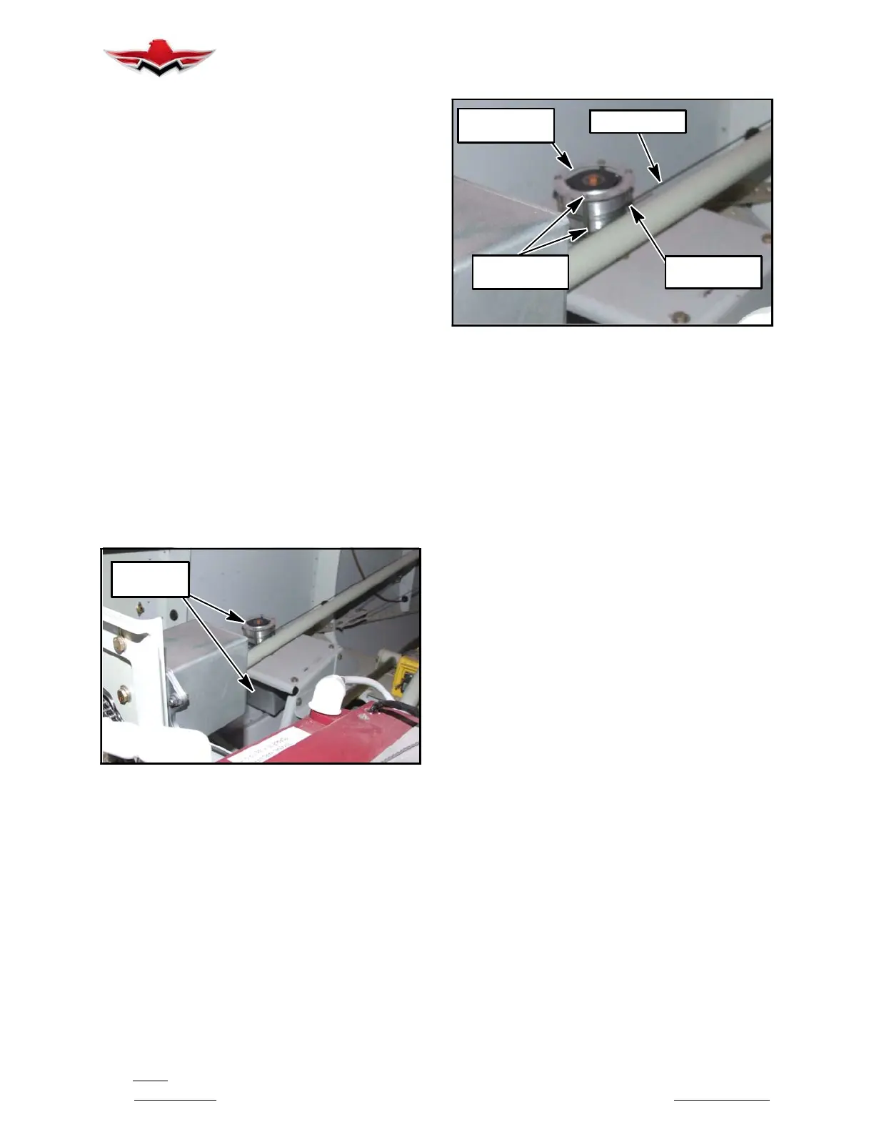
B. Loosen bridle cable by turning turn barrel on
(AFT) portion of cable to obtain adequate slack to re-
move cable from pitch trim servo capstan.
BRIDLE CABLE
CENTER BALL
CABLE GUARD
COVER
DOWEL
SCREWS AND
BRIDLE CABLE
PITCH SERVO BRIDLE CABLE CENTER
FIGURE 22- 8
C.
Remove Pitch Servo Mount (4) attaching
bolts and remove from Aircraft
.
3. Pitch Servo Mount Clutch Adjustment
A.
For instructions on checking the slip- clutch,
refer to the GSM Slip- Clutch Setting Procedure in
the GSA 8X/GSM 86 Installation Manual (Garmin
part number 190- 00303- 83 or later revision). To de-
termine the slip-clutch torque setting refer to Figure
22- 9. If a slip clutch is found to be out of spec, it
should be replaced with a new slip clutch. GSM 86
slip clutches are not settable once manufactured.
4. Installation of Pitch Servo and Servo Mount
A.
Install Pitch servo mount to bracket with origi-
nal (4) bolts. Refer Figure 22- 9 Torque Chart for
Specifications (Clutch Kit 011-02147-09).
B. Use a brush or applicator, apply a thin coat of
grease to the servo output gear. Use Aeroshell
33MS or Aeroshell 17. Clean and apply grease to
output gear every 1000 hours or 3 years.
C. Install Pitch servo to servo mount with original
(2) bolts. Refer Figure 22- 9 Torque Chart for Spe-
cifications.
D. Locate bridle cable center ball so that it is fac-
ing normal to pitch tube.
E. Wrap cable one full wrap in each direction.
Use turn barrel to set cable tension, refer Figure
22- 9 Torque Chart for Specifications.
F. Install cable guard cover and secure with origi-
nal (4) attaching screws and dowels. Check for align-
ment (see Figure 22- 8).
G. Visually inspect the connectors to ensure
there are no bent or damaged pins. Repair any dam-
age, and connect pigtail connector.
H. Move controls forward and aft through full
range of motion ensuring correct position and move-
ment of cable and capstan. Ensure capstan-to-cable
payoff angle does not exceed or equal 3 degrees. If
22-10-03
 Loading...


