MOONEY INTERNATIONAL CORPORATION
M20V SERVICE AND MAINTENANCE MANUAL
Page
Date
7
MAR 2017
Rev Date
TROUBLESHOOTING
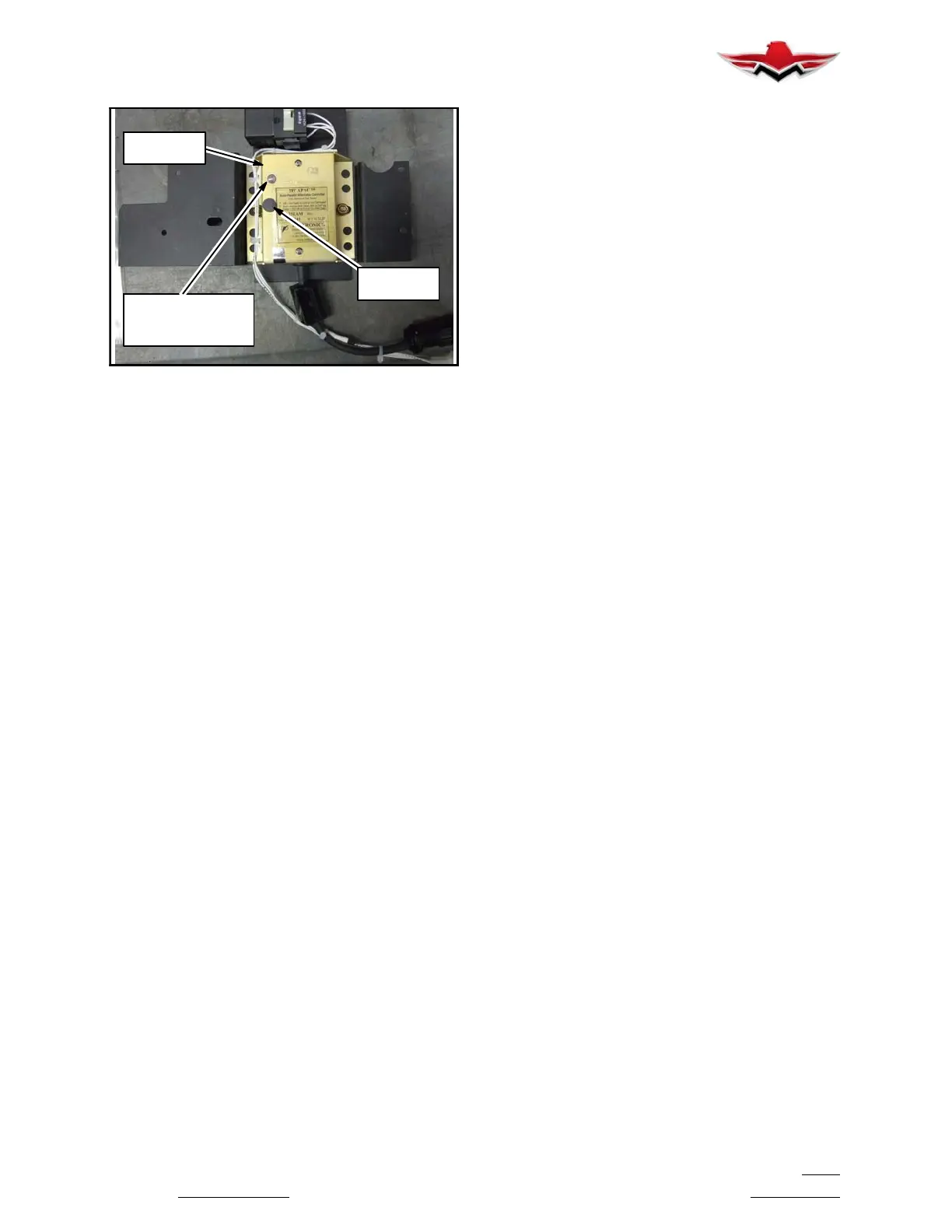
LIGHT
(TSL)
APAC
UNIT
ADJUST
POT
TROUBLESHOOTING LIGHT (TSL)
FIGURE 24- 1
Battery Off- Line Failure Regulation (BOLR) – The
PAC’s design allows it to regulate the Buss voltage with
the battery off- line. This feature allows the system to
carry electrical load if the battery fails or the battery
relay fails to open. The APAC provides RVP and GFP
functions while the system operates in the BOLR
mode.
Remote Voltage Sensor & Protection (RVP) – The RVP
senses the voltage at the battery terminal of the alter-
nator or the Buss to provide better voltage regulation
and eliminate flickering charge- meter and panel lights
problem. Losing or opening the RS wire will turn off the
APAC, taking the alternator off- line.
Over Voltage Protection (OVP) – The OVP circuit moni-
tors the Buss voltage for excessive voltage (OV) that
could damage batteries and other voltage sensitive
equipment. If it senses an OV condition, it opens the
current path to the Voltage Regulator (disabling the al-
ternator’s field) and turns on the unit’s TSL red and the
AOI light in the cockpit. After OV trip, the APAC must be
reset by turning off and then on the alternator field
switch.
Field- to- Ground Short Protection (GFP) – If the alter-
nator’s field shorts to ground, the field- to- ground, the
field- to- ground short protector will deactivate the volt-
age regulator, as well as switch on the unit’s red TSL
and the AOI light on the instrument panel.
Alternator Out Sensor (AOS) and Indicator (AOI) – The
AOS monitors the alternator’s Aux terminal voltage
(from pin 2) to identify if the alternator is on- or off- line.
If the alternator is off- line, the AOI light, on the instru-
ment panel, connected to pin 6 will come on. AOI will
come on under these conditions:
- Loss of power to The APAC
- Over Voltage trip condition
- Loss of or open Remote Voltage Sense
- Loss of or open Aux Voltage Sense
- Field to Ground Short Fault
- Alt Off- Line
Troubleshooting Light (TSL) – Located on the front
plate of the unit, alerts the user to the condition of the
alternator/APAC system.
A Red TSL with the Bat & Alt switches on, means
there is an internal or external ground short in the alter-
nator field circuit. Some alternator’s field short to
ground under a “flying short” condition, which usually
occurs when engine is rotating at higher RPM and not
when the engine is off or rotating at a lower RPM.
A Green TSL, with the engine running, means there
is power coming out of the APAC. With the TSL Green,
a Buss voltage of 28.2V to 28.8V indicates a system
that is operating correctly, and a sustained Buss volt-
age of 20V to 25.6V means an open alternator field wire
or internal alternator field open fault (including “flying
open”). In a flying open condition, the alternator may in-
dicate a “good” field resistance reading when the en-
gine is off or the alternator’s pulley is turning at a lower
RPM, but open at a higher RPM.
NO Light on the unit, with the master switch ON,
means a damaged power input device (switch, circuit
breaker, or wiring) or APAC.
MAINTENANCE INSTRUCTIONS
The APAC is not field serviceable or repairable beyond
what is prescribed in this manual. Should the APAC not
function as described in the following, “How the System
Works,” and the service technician or engineer cannot
solve the system’s problem by following the Trouble-
shooting notes, return the unit to Zeftronics or its ap-
proved repair station.
During each annual inspection perform the following
Installation/Maintenance Instructions.
Installation/Maintenance Instructions (refer to Fig.
24- 2)
1. If applicable, disconnect and remove (except for
ICA activity described below) the present ACU/VR.
Verify that the system wiring is as shown below (the
OEM or installer may change the system wiring to suit
their application as long as the APAC’s input and output
functions remain as indicated).
2. Measure the Alternator’s field Resistance between
pin 7 (of airframe’s VR connector) and Ground. A resist-
anceof10to20Ω is normal. If the resistance is less
than 8Ω or greater than 20Ω, check the Alternator or the
wire from pin 7 to the field. 0Ω indicates a short to
ground between the field wire or field winding.
3. Verify that the resistance of the Alt switch is
0- 0.1Ω. A voltage drop test during the post installation
test will serve the same purpose.
24-31-02


 To Next Page
 Loading...