MOONEY INTERNATIONAL CORPORATION
M20V SERVICE AND MAINTENANCE MANUAL
Page
Date
8
MAR 2017
Rev Date
B
ALT
8
8
A25EAM
1
5
1
5
6
6
A01
2
2
7
7
9
9
1A C/Bkr or Fuse
Fld
Aux
Bat
* Depending on the ALT Fld
C/breaker may be 2 to 10A
Alt Out
Alt
5A*
Alt Fld
BUS BAR
50A - 125A
A
Bat
NOT
USED
Sw
Relay
Bat +
Sw
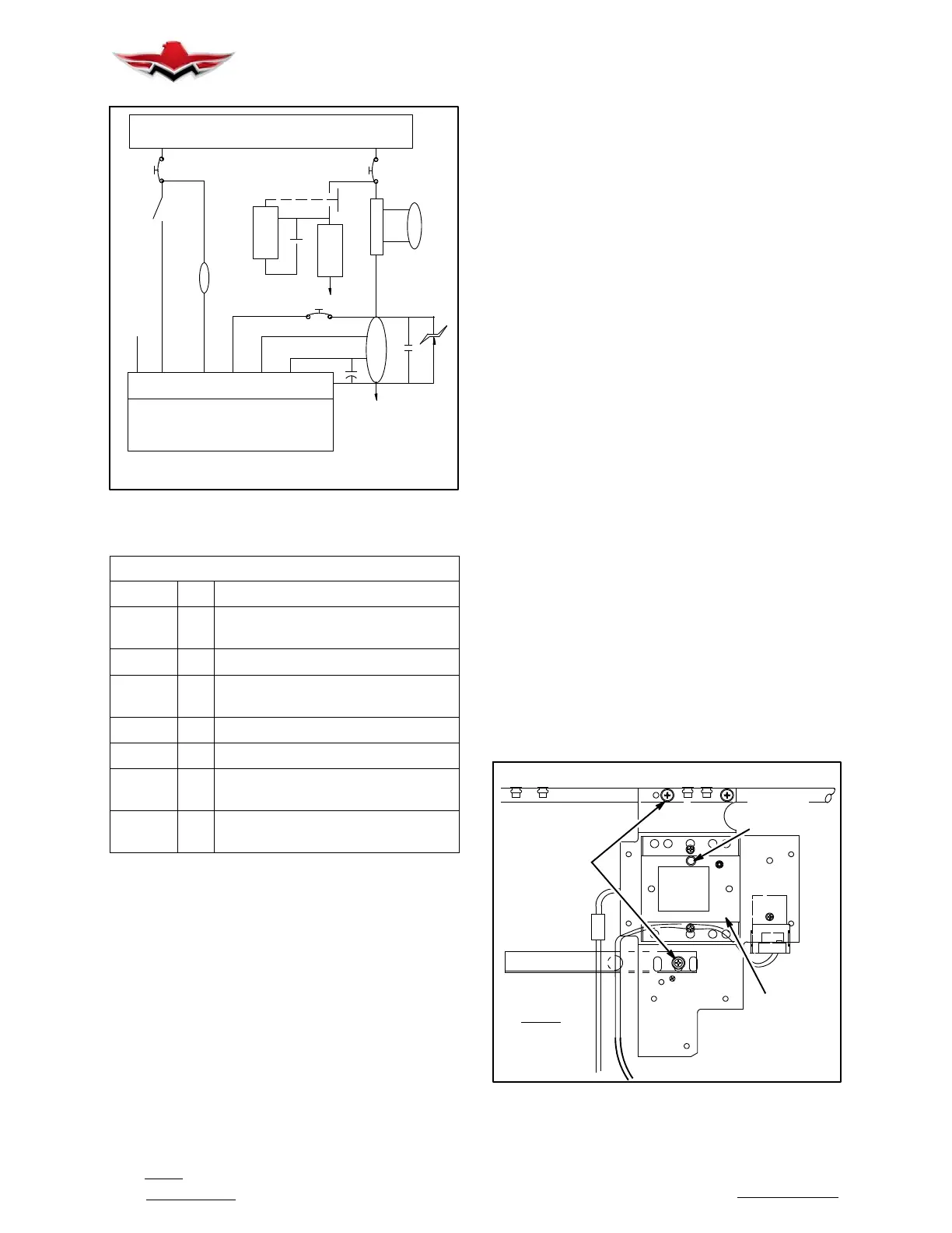
TYPICAL SYSTEM WIRING
FIGURE 24- 2
TYPICAL SYSTEM WIRING CHART
Wire Pin Function or Connect to
Green 1 Pin 1 (parallel wire) to second ACU
(Not Used)
White 2 Alt Aux terminal for Alt Out Sense
Red 5 Alt Switch or Alt field circuit break-
er
Yellow 6 Alternator Off- line Indication
Blue 7 Alternator Field
Orange 8 + Remote Sense to Alt BAT termi-
nal
Black 9 - Remote Sense to Alternator
case/Gnd
4. Spray contact cleaners in the mating connectors
(the airframe and APAC).
5. Check the condition of the wires in the Electrical
Charging System (ECS); from the APAC to the Master
Switch, Field Breaker, Alternator Main Output Breaker,
Battery, Shunts, Relays, and other related compo-
nents. Replace frayed or cracked wires. Clean/Re-
place oxidized contacts and connections.
6. Mount the APAC in a location where the mechanic
will have easy access to view the TSL (Troubleshooting
Light) on the unit. The TSL is located on the front sur-
face of the APAC.
7. Connect the APAC to the system.
8. Perform the Post Installation Test Procedure.
POST INSTALLATION TEST PROCEDURE
1. Turn On the Alt & Bat switches, observe that the
AOI light is on.
2. On the APAC, the TSL should be Green. If the TSL
is Red, the Field is shorted to ground.
3. If the TSL is Off, measure the voltage on pins 5 and
7. Read Battery voltage on pin 5 and 1- 2 volts less on
pin 7.
4. If the steps 3 & 4 are successful, perform step 5. If
not, repeat Installation/Maintenance Instructions pro-
vided above.
5. Start the engine, and at 1500 RPM, measure to
Buss voltage of 28.2- 28.7V. Also see ADJUSTING
VOLTAGE (APAC).
A. If the Buss voltage exceeds these limits, check
for voltage drop across the 5A breaker, the Alt switch,
and pre- APAC wires.
B. If the AOI light is On but the Buss voltage is at
28.2- 28.7, check for an open or grounded wire from pin
2 to the AUX or STA terminal on the Alternator.
C. If the AOI light is On and the TSL is Green (the
Buss voltage is below 26V), check for an open wire
from pin 7 to the Field terminal on the alternator or an
internally open alternator Field.
ADJUSTING VOLTAGE - (APAC)
1. If voltage adjustment is required:
A. From under dash, located behind MFD panel re-
move screws (3) mounting bracket and APAC assem-
bly (refer to figure 24-3).
B. Remove the adjustment pot cap on (APAC) volt-
age regulator.
C. Using a small screwdriver adjust to Buss volt-
age of 28 volts @ 1000 rpm.
D. Test Buss voltage at Full Power 2500 rpm to in-
sure no overvoltage.
REMOVE
(3) SCREWS
LOOKING UP
UNDER DASH
VOLTAGE
REGULATOR
(APAC)
VIEW
ADJUSTMENT
POT CAP
VOLTAGE REGULATOR (APAC)
FIGURE 24- 3
24-31-02


 To Next Page
 Loading...