MOONEY INTERNATIONAL CORPORATION
M20V SERVICE AND MAINTENANCE MANUAL
Date
MAR 2017
Rev Date
Page
5
32-00-00 - GENERAL
The landing gear is operated by an electrical, motor
driven, actuator. Travel during the extend and retract
cycle is controlled by down and up limit switches lo-
cated beneath the floorboard under the pilots seat.
Power is supplied to actuator through a set of relays ac-
tuated by the gear selection switch. The gear selection
switch is located on instrument panel in front of the pilot.
The actuator worm gear ball nut is connected to retract
bellcrank which is connected to push- pull retract tubes
and bellcranks throughout entire retraction system.
The gear legs are constructed of welded, chrome- mo-
lybdenum, tubular steel, heat treated for greater
strength and wear resistance. Main gear attaching
points have bushings installed in gear mounting box at-
tached to wing spars. The steerable nose gear mounts
to the cabin tubular steel frame.
-NOTE-
Heat treated components should NOT be re-
paired; replace them.
The main gear wheels have hydraulic disc brakes with
a parking brake valve incorporated into system.
Rubber discs in all gear leg assemblies absorb the
shock of landing and taxiing.
LANDING GEAR EMERGENCY EXTENSION SYS-
TEM.
Emergency gear extension is available through a
manual override system. This system is built into the
actuator unit. The disengage controls are located aft
and between front seats.
LANDING GEAR WARNING SYSTEM
The landing gear warning system provides pilot with a
gear warning “Voice alert” “Check Gear” that landing
gear is not down and locked when throttle is retarded
and landing gear is still up. The warning system is acti-
vated when throttle is retarded approximately 1/4 inch
from idle position. When landing gear is down and
locked, the electrical circuit is opened and the alert is
stopped. This warning switch is mounted on engine
throttle housing and can be adjusted for the proper set-
ting by loosening screw and repositioning switch (Refer
to the Garmin G1000 Cockpit Reference Guide for de-
scription).
BRAKE SYSTEM
The brake system is hydraulically operated by depress-
ing brake pedals mounted on pilot’s rudder pedals.
(Dual brake system is optional for co- pilot). Individual
wheel brakes are available by depressing either left or
right pedal. Parking brakes are actuated by depressing
both brake pedals and pulling parking brake control
cable knob. This cable actuates lever on parking brake
valve and traps hydraulic fluid from valve to wheel cylin-
ders, therefore, holding pucks to brake discs. Release
parking brake by pushing parking brake knob IN. This
releases hydraulic pressure at wheel cylinders and re-
leases brake discs.
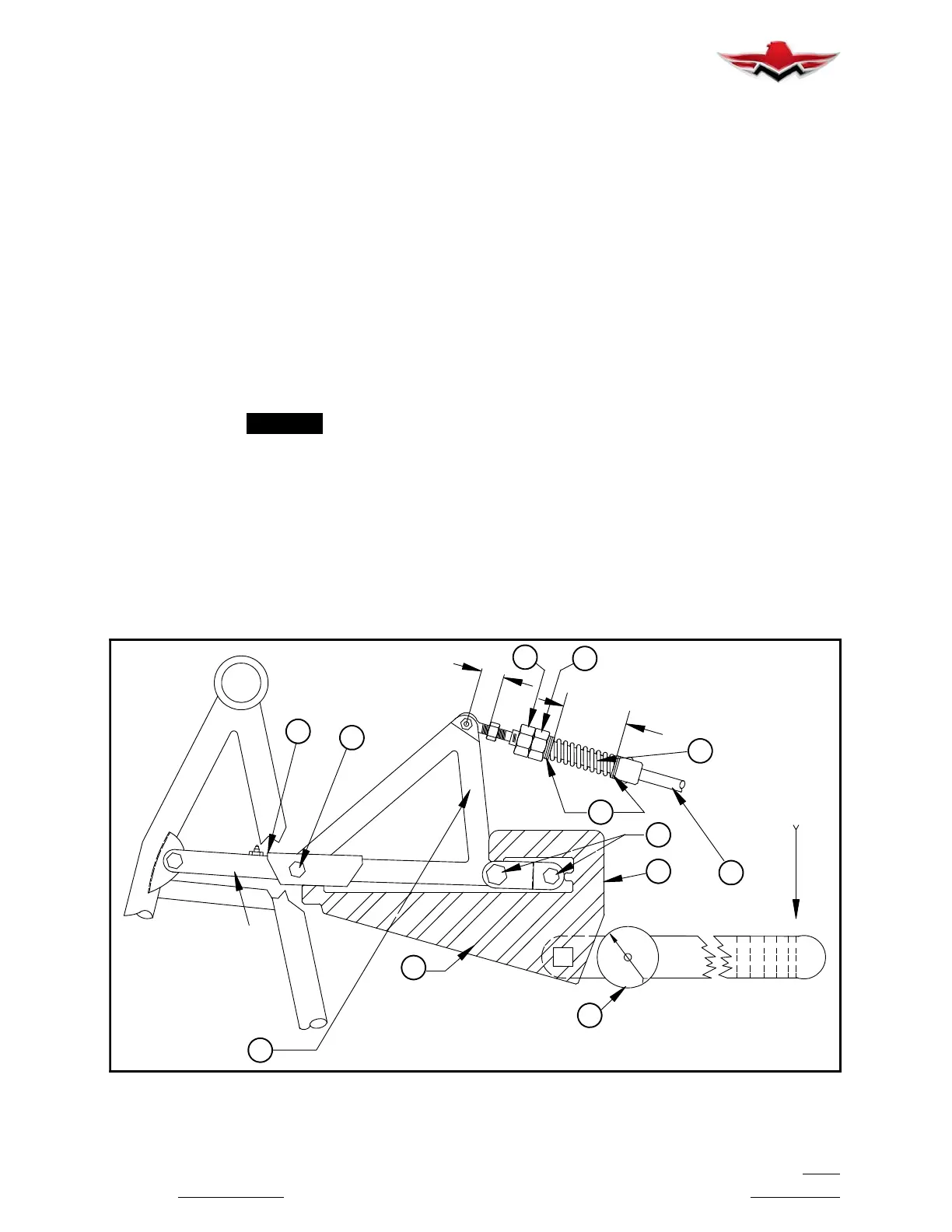
1.56 (MAX.)
LEFT MAIN GEAR
(VIEW LOOKING FWD)
LINK
RETRACTION
RETRACTION
TRUSS G
TOOL
T
P
4
TORQUE
WRENCH
R
E
250 - 280
INCH LBS.
R
C
O
F
1.68
Z
S
H
NOM.
X
Y
V
W
RIGGING
030007- 100
RETRACTING
TUBE
MAIN LANDING GEAR RIGGING TOOL APPLICATION
FIGURE 32-1
32-00-00
 Loading...


