MOONEY INTERNATIONAL CORPORATION
M20V SERVICE AND MAINTENANCE MANUAL
Date
MAR 2017
Rev Date
Page
6
32-10-00 - MAIN LANDING GEAR AND DOORS
32-10-01 - MAIN GEAR REMOVAL
1. Raise aircraft on jacks.
2. Partially retract gear as described in Section
32- 60- 01, paragraph 1.
3. Disconnect gear door links and brake lines. Cap all
lines and fittings.
4. Remove gear door and mud guard (if desired).
5. From (Fig. 32- 1), detach main gear retracting tube
(V), from retracting truss (G), and remove bolts (H) from
retracting truss mounting block.
6. Remove three screws from small skin panel cover-
ing aft portion of landing gear leg trunnion and bearing
bracket from bottom of wing. Slide panel from position
to gain access to bracket bolts.
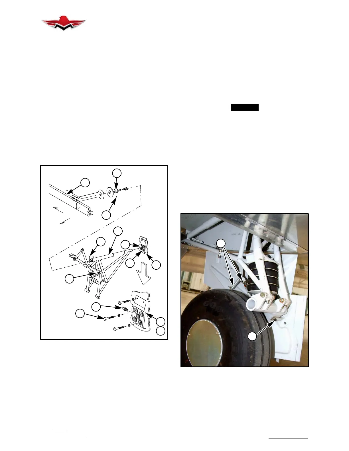
7. Remove mounting bolts (2) (Fig. 32- 2) from rear
gear leg trunnion shaft mounting block assembly (4) at
stub spar (5). Shims (6) may fall out.
FWD
INBD
DETAIL A
3
8
7
8
1
8
4
5
4
6
2
8
8
GEAR REMOVAL
FIGURE 32-2
8. Slide aft bearing block (4) down (Fig. 32- 2).
9. Slide front bearing block on main spar (3) down/aft
and remove.
10. Slide gear assembly (1) aft until clear of front
bearing (7) on main spar (3). Carefully remove gear as-
sembly from wing.
11. Identify all components removed, and DO NOT
inter- mix right and left gear components.
12. DO NOT attempt to repair any heat treated com-
ponent of main landing gear assembly.
32-10-02 - MAIN GEAR INSTALLATION
1. Lubricate wheel bearings, retraction linkage and
fore and aft trunnion bearings prior to installation at lu-
brication fittings (8) (Fig. 32- 2). Refer to Section
5- 20- 07 for recommended lubricants.
2. Installation of main gear is exact reversal of main
gear removal procedure.
-NOTE-
Torque 510078- 001, - 003 or - 005 bolts (at Spar/
Truss Attach Bracket) to 270 to 300 in. lbs.
3. Check fore and aft movement of gear in bearing
blocks. Maximum allowable movement is .020. Shim
excess by inserting maximum of two shims (6) between
two rear blocks. The side to side Maximum front bear-
ing MLG leg trunnion clearance .010 inches and Mini-
mum front bearing MLG leg trunnion clearance .001
inches. Maximum rear bearing MLG leg trunnion clea-
rance .016 inches and Minimum rear bearing MLG leg
trunnion clearance .001 inches. If .010 inch additional
clearance is above the mentioned production limits, it
should be considered out of service limit.
4. Temporarily attach gear door link rods to gear leg
brackets.
B
A
MID- GEAR DOOR ADJUSTMENT POINTS
FIGURE 32-3
5. Retract gear while checking for binding in door link-
age and proper contact of gear door edges with wing.
DO NOT make final gear door adjustments until gear
has been rigged (Ref. 32-30-02).
32-10-00
 Loading...


