MOONEY INTERNATIONAL CORPORATION
M20V SERVICE AND MAINTENANCE MANUAL
Date
MAR 2017
Rev Date
Page
7
32-10-03- MAINGEARDOORRIGGING
1. Raise aircraft on jacks. See Section 7- 10- 00.
-NOTE-
Gear system must be properly rigged prior to
gear door rigging, see Section 32- 30- 01.
2. Normally, once doors are installed at factory, no
further adjustment should be required. However,
should mid- gear doors be removed for any reason, the
following rigging procedures should be used when rein-
stalling them:
A. Disconnect outboard doors at forward and aft
linkages (B) (Fig.32- 3).
B. Disconnect inboard doors at forward linkage
and springs (A) (Fig.32- 3).
C. Raise gear electrically to full UP position.
D. Forward leading edge and aft trailing edge of
mid gear door should be tight against wing skin.
Spacers (A) (Fig. 32- 3) should be added or removed
as required to obtain a good fit with no binding or distor-
tion with gear in UP position. AN960- 10 or AN960- 416
washers may be used as spacers.
3. Reconnect outboard and mid- gear doors and
check that doors are faired with wing skin/wheel well
opening and that there is no binding or distortion where
links attach to door. Adjust linkage/spacers if required.
(Fig. 32- 3) Extend gear to adjust, then retract to check
adjustment.
4. Check main gear overcenter preload torque for
proper values. Re- rig entire landing gear sy
stem, if
necessary (See Section 32- 30- 02 & 32- 30- 03).
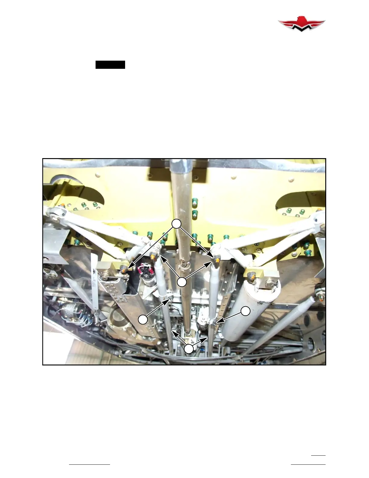
M
E
J
H
L
MAIN GEAR RETRACTION TUBE ADJUSTMENT POINTS
FIGURE 32-4
32-10-04 - INBOARD DOOR RIGGING
1. Adjust inboard door link to close doors with “0” gap
leading edge full up pos
ition. Doors must be closed with
gear extended and retracted. If door is not closed in
both positions, refer to landing gear rigging procedures
in Section 32- 30- 02. Any adjustment to rod end on
main retract tube (L) (Fig. 32- 4) and rod end on retract
tube (V) (Fig. 32- 1) is at a 2 to 1 ratio, respectively; this
adjustment will change rigging values. Re- check pre-
load values.
EXAMPLE: If inboard gear door is open a small amount
when landing gear is down, but closed when gear is UP.
- Adjust by turning retract tube (V) rod end IN 1/2 turn,
and retract tube (L) (Fig. 32- 4) rod end OUT 1 turn.
32-10-03
 Loading...


