MOONEY INTERNATIONAL CORPORATION
M20V SERVICE AND MAINTENANCE MANUAL
Date
MAR 2017
Rev Date
Page
8
EXAMPLE: If inboard gear door is closed with landing
gear in DOWN position, but open a small amount with
landing gear in UP position. - Adjust by turning retract
tube (V) (Fig.32- 1) rod end OUT 1/2 turn, and retract
tube (L) (Fig.32- 4) rod end IN 1 turn.
2. Tighten jamb nuts and reconnect springs on in-
board gear door bellcrank (A) (Fig.32- 5).
-NOTE-
Do not rig doors shut more than necessary as
this may result in higher actuator loads than nec-
essary.
3. Adjust outboard door link to close all gap at leading
edge of door. If door is rigged too tight, skin will be under
stress (concave) at the point where the linkage is at-
tached to door. It could also cause mid and inboard
doors to gap open.
Verify Door Stop Rigging prior to continuing with Step 4
of this procedure:
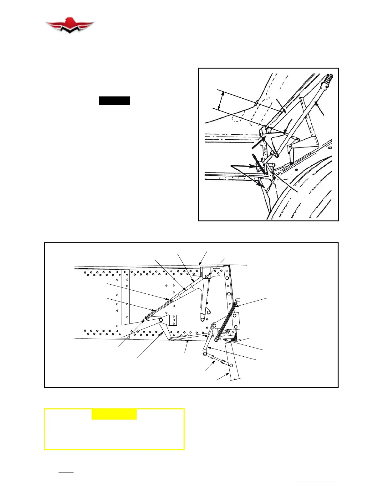
DOOR STOP RIGGING/CHECK
A. Extend or retract landing gear until points “A,”
“B,” and “C” are in alignment as shown in Figure 32- 6.
Verify that Stop Bolt of Stop just contacts Arm on Bell-
crank “A.”
If contact puts “no load” on Rod “A,” then proceed to
Step 4. No load on the Rod may be verified by being
able to move the Rod by finger pressure or rotation. If
load on the Rod is indicated, or no Bellcrank to Stop
contact is made, proceed with Steps B and C.
1.35”
E
D
V
A
C
B
MAIN INBOARD GEAR DOOR RIGGING
FIGURE 32-5
SPRING
STOP/STOP BOLT
BELLCRANK “A”
INBOARDGEARDOOR
ROD
ROD “A”
BELLCRANK
POINT “C”
MAIN SPAR REF.
ROD
BELLCRANK
REFERENCE LINE
POINT “B”
POINT “A”
ALIGNMENT
DOOR STOP RIGGING
FIGURE 32-6
-CAUTION-
Stop Bolt must be screwed all the way into the
housing portion of the Stop prior to beginning
of Door or Stop rigging if rigging adjustments
are required.
B. Extend Stop Bolt of Stop until contact with Arm
on Bellcrank “A” is made. Continue extending Bolt until
there is no load on Rod “A”. No load on the Rod may be
verified by being able to move the Rod by finger pres-
sure or rotation.
C. Tighten Jam Nut on Stop.
32-10-04
 Loading...


