MOONEY INTERNATIONAL CORPORATION
M20V SERVICE AND MAINTENANCE MANUAL
Date
MAR 2017
Rev Date
Page
9
D. Repeat steps B and C for other side’s landing
gear.
E. Continue to Step 4 of Inboard Gear Door Rig-
ging.
4. Cycle gear manually and electrically while inspect-
ing for clearances and proper operation. Re- check
landing gear system rigging values.
5. Remove aircraft from jacks.
6. Return aircraft to service.
-NOTE-
To remove INBOARD GEAR DOORS, use a sharp-
ened punch less than .093 dia. or a short piece of
hinge pin to open crimped hinge assembly pin
hole.
A
ASSIST BUNGEE
FIGURE 32-7
32-10-06 - ASSIST BUNGEE REMOVAL/INSTAL-
LATION
REMOVAL
1. Raise aircraft on jacks and remove smooth belly
access panel(s).
2. Retract landing gear until rigging pin holes (A) (Fig.
32- 7) line up on bungee assembly and insert 3/16 in.
pin.
3. CAREFULLY BUMP gear UP, with the gear safety
bypass switch, until there is zero load on bungee as-
sembly rod end. Remove AN3 bolt at rod end and AN4
bolt at block; remove bungee assembly.
INSTALLATION
1.
Rais
e aircraft on jacks. See Section 7- 10- 00.
2. Compress replacement bungee (250 lbs.) to align
installation rig- pin holes. Insert 3/16” pin.
3. Retract gear.
4. Pull gear down with emergency extension until
main retract bellcrank and rod end bungee line up.
Install proper length AN3 bolt through rod end bearing
and proper length AN4 bolt through block. Torque nuts
and safety.
-CAUTION-
Bump gear up, CAREFULLY, just to take load
off 3/16 in. installation pin at (A). Remove pin
from (A) (Fig. 32- 7).
5. With bungee installed, re- check preload per steps
30 thru 34 of Section 32-30-02.
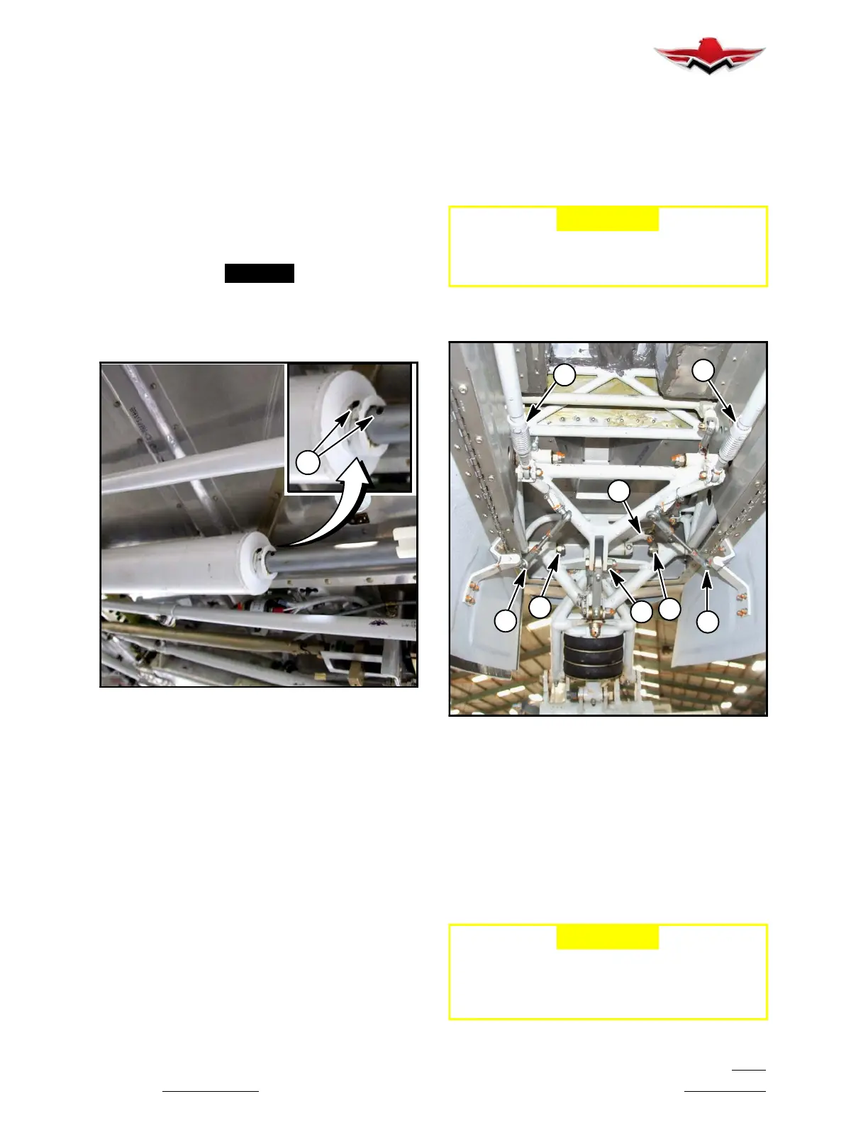
F
F
H
J
E
D
B
A
NOSE GEAR RETRACTION TUBE ADJUSTMENT
POINTS
FIGURE 32-8
32-20-00 - NOSE GEAR AND DOORS
32-20-01 - NOSE GEAR REMOVAL
1.
Raise aircraft on jacks
per Section 7-10-00.
2. Partially retract gear as described by Section
32-60-01.
3. Disconnect link (A) on nose gear truss assembly
(Fig. 32- 8).
-CAUTION-
Eccentric bushings at (J) (Fig. 32- 9) may have
a flush head screw installed on either side.
This flushhead screw and counter sunk eccen-
tric MUST BE re- installed at same locations.
32-10-06
 Loading...


