MOONEY INTERNATIONAL CORPORATION
M20V SERVICE AND MAINTENANCE MANUAL
Date
MAR 2017
Rev Date
Page
26
-NOTE-
Check nose gear leg assembly for towing dam-
age. Replace if any dent exceeds 1/32 inch.
Twin limiter pads and adjustable stops (7) (Fig. 32- 23)
are installed on the nose gear leg assembly (A) to pre-
vent towing/turning damage to the leg assembly.
1. Every 100 hours remove cotter pin (1) (Fig. 32- 23)
and retorque nut (2) to 270- 300 inch lbs. Check holes
in leg assembly where pivot bolt (3) is located for any
wear. If holes are worn, replace leg assembly.
-CAUTION-
Bolt (10), washers and nut (9) (Fig. 32- 23) must
be installed as shown, from rear to front.
2. Rod end bearing (4) (Fig. 32- 23) should be in-
spected at least every 100 hours for any damage or
bending.
TUBULAR STRUCTURE
LEG ASSY.
NOSE GEA R
9
5
4
RUDDER/STEERING
TORQUE TUBE
10
3
A
2
7
1
8
6
720095- 15
ARM ASSY
720095- 17
SHAFT
720020- 501
COLLAR
720013
SHIMS
720095- 1
HORN ASSY
DETAIL ITEM (5)
NOSE WHEEL STEERING
FIGURE 32-23
3. Check the steering horn assembly (5) collars and
spacers for looseness. Replace any bushings or
spacers that are worn. Shim steering horn as follows;
Run nose gear through full left travel and hold, measure
gap between 720095-15 arm assy and 720095-17
shaft assembly, record measurement. Check for full left
travel between rudder and nose gear assembly.
720095-15 arm should not contact 720095-17 shaft in
full left travel. It is cause for rejection if binding occurs.
Next; Run nose gear assembly through full right travel
and hold; measure gap between 720095-15 arm and
720020-501 collar and record measurement. Check for
full right travel between rudder and nose gear assem-
bly. it is cause for rejection if binding occurs. A gap of
.003 to .020 is acceptable as is on either side of
720095- 15 arm assembly. If gap is greater than .020
on either side of 720095-15 arm; shim as required with
720013-(x) shims to maintain .003 to .020 gap.
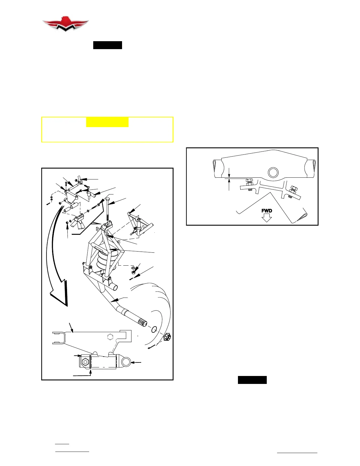
MAX. ALLOWABLE
0.020” GAP
TYP. BOTH SIDES
NOSE WHEEL STOP GAP ADJUSTMENT
FIGURE 32-24
4. Adjust turn limiter stop bolts (7) to contact cross
member (8) (Fig. 32- 23) of truss assembly (.020 gap
permissible) (Fig. 32- 24) when rudder is at its extreme
left and right travel position.
32-50-02 - NOSE GEAR STEERING AND TRACK-
ING
1. Level aircraft as described in Chapter 8.
2. Center nose wheel.
3. Place plumb line over and forward of nose gear
trunnion (see Fig. 32- 25).
4. Measure forward from aft edge of plumb line to
axle center line, assembled axle center- line to fall on
station - 13.375” +/- .25”.
5. Add spacer(s) under collar to reposition the axle if
required. Refer to IPC for parts number breakdown.
-NOTE-
Some collars have holes drilled off center and
may be turned over to change axle position.
6. Run gear through retraction/extension cycle.
Check nose gear door and wheel well tire clearances.
Re- rig if required.
32-50-02
 Loading...


