MOONEY INTERNATIONAL CORPORATION
M20V SERVICE AND MAINTENANCE MANUAL
Date
MAR 2017
Rev Date
Page
27
SPACER
COLLAR
TRUNNION
32- 50- 02
PLUMB LINE
PARAGRAPH 4
CENTER
LINE
AXLE
SEE
NOSE GEAR
NOSE WHEEL LOCATION
FIGURE 32-25
32-50-03 - NOSE GEAR TOWING LIMITS INDICA-
TOR RIGGING
TOWING LIMITS
TURN
DECAL
INDICATOR
Decal must be
placed at center
of Horizontal Nose
NOTE:
HORIZONTAL
NOSE GEAR
TRUSS TUBE
Gear Truss Tube
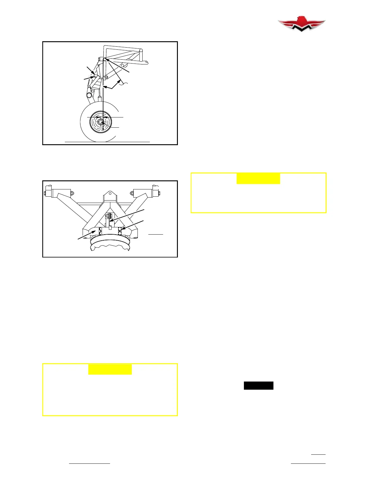
NOSE GEAR TOWING LIMITS INDICATOR
FIGURE 32-26
An indicator assembly, comprised of an indicator and
decal, is attached to the Nose Gear Leg Assembly (Fig.
32- 26) to indicate turning limits of nose gear. The decal
provides a visual indicator of Nose Gear position in re-
lation to turn limitations. This decal must be placed at
center of horizontal nose gear truss tube (if replaced).
To rig the indicator assembly:
With landing gear fully connected and rigged, roll air-
craft forward along a straight line for at least ten feet un-
til castering nose wheel is centered. Loosen the Indica-
tor assembly at the Gear Leg and align Indicator to
center of decal (not contacting tube).
-CAUTION-
Exercise care not to turn nose wheel past its
normal swivel angle of 11
left or 13
right of
center.
Exceeding the turn limits shown on turn indica-
tor may cause structural damage. Refer to
section 9-10-00 for Towing instructions.
32-60-00 - POSITION AND WARNING
32-60-01 - ELECTRIC GEAR S AFETY DEVICES
The gear switch operates the landing gear actuator re-
lay. Pulling the wheel- shaped knob out and moving it to
the upper detente raises the gear.
The up- limit switch will stop the gear in its retracted po-
sition. Moving the control knob to its lower detente low-
ers the gear. The down limit switch will stop the gear ac-
tuating motor when the proper force is exerted to hold
the gears in the down- and- locked position. Refer to
Section 32-30-02 for proper limit switch rigging. The
gear down- and- locked position is indicated by:
1. Illumination of the green gear down G1000 annun-
ciation light. The GEAR DOWN G1000 annunciation
light is dimmed when ever the Navigation Light Switch
is ON.
2. The gear warning “Voice Alert” will not sound with
the throttle retarded within 1/4 inch of idle position.
3. The indicator marks will be aligned on the visual
gear- position indicator.
-CAUTION-
When running gear up or down electrically DO
NOT use circuit breaker as a switch. Partial re-
traction or extension may be accomplished
electrically as follows:
1. Place Master Switch in OFF position.
2. Move gear switch to GEAR UP or GEAR DOWN as
desired.
3. Momentarily actuate Master Switch until gear is in
desired position.
32-60-02 - LANDING GEAR WARNING SYSTEM
The landing gear warning system consists of:
1. Landing gear position lights:
“GEAR DOWN” - GREEN light on G1000 annunciation
and Gear Down Position indicator light on floor
“GEAR UNSAFE” - RED light on G1000 annunciation
“GEAR IN TRANSIT” – RED light on G1000 annuncia-
tion
“GEAR UP” - No lights
2. A gear warning “Voice Alert” is actuated when gear
control switch handle is UP and the throttle is less than
1/4 inch from idle position. Check warning for volume in
flight periodically. Warning will sound if gear is not
DOWN and LOCKED even if switch is in DOWN posi-
tion or if airspeed is below 60 5 KIAS and gear switch
is in UP position.
-NOTE-
To prevent inadvertent Gear Warning operation
under high humidity conditions, cover leads on
the Throttle Switch-Gear Warning with Dow Corn-
ing 738 Electrical Sealant. Switch unit is Micro
Switch 1SE1-T.
32-50-03
 Loading...


