MOONEY INTERNATIONAL CORPORATION
M20V SERVICE AND MAINTENANCE MANUAL
Date
MAR 2017
Rev Date
Page
28
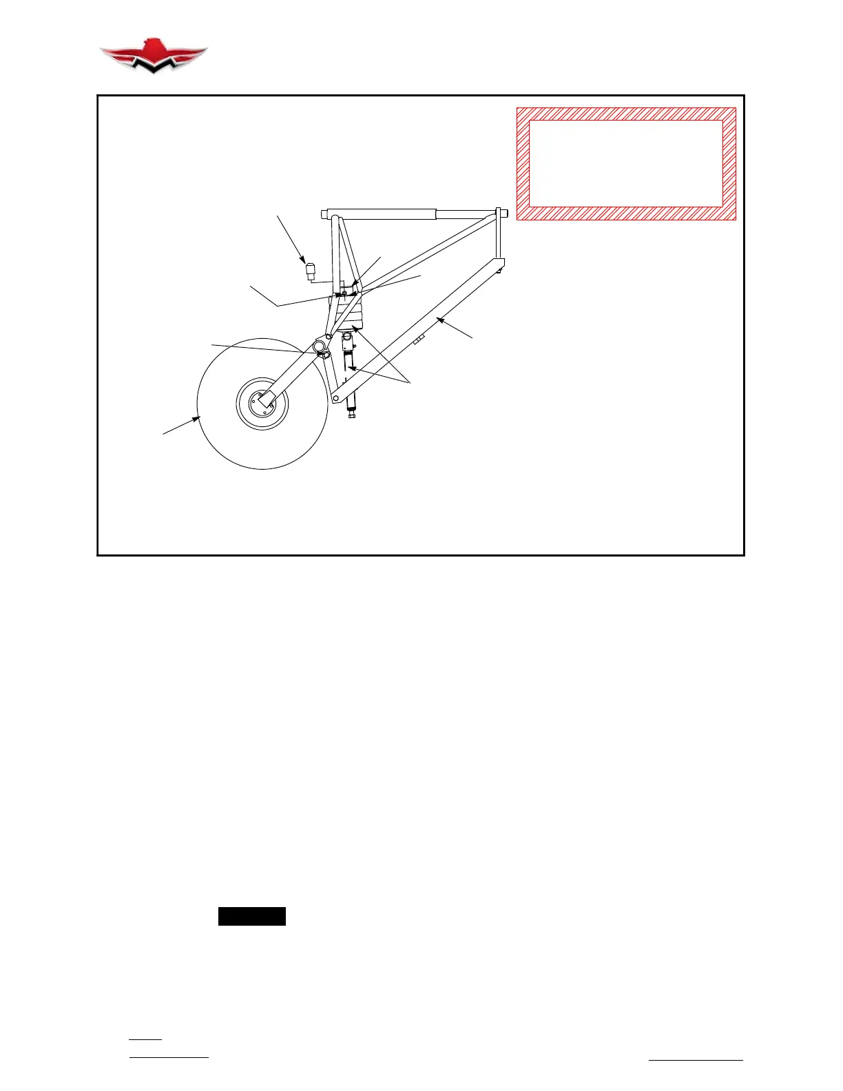
030011- 14 PAD
PLACE IN END OF SHOCK LINK
FOR GUIDING SHOCK LINK
INTO HOLE IN LEG
COMPRESS UNTIL HOLES ALIGN
INSHOCKLINK&HOLEINLEG
MAIN TIRE
AN9- 25A BOLT
MS21044N9 NUT
FINGER TIGHT NUT
WHILE CHANGER IS
IN OPERATION
NOTE: TORQUE SHOULD NOT EXCEED 60 FT - LB WHEN SHOCK DISK
DO NOT BE IN POSITION BETWEEN
COMPRESSOR TOOL AND FLOOR
WHEN COMPRESSOR TOOL IS IN
OPERATION.
A
GEAR LEG. IF TORQUE IS BEYOND 60 FT- LB, CHECK FOR AXIS
ARE COMPRESSED AT ALIGNMENT OF HOLES IN SHOCK LINK &
APPLICATION & ATTACHMENT OF - 501
C
AXIS OF SHOCK LINK & JACK SC REW MUST ALIGN
MLG DISC COMPRESSOR
MIS- ALIGNMENT.
B
WARNING
MAIN GEAR SHOCK DISC REPLACEMENT
FIGURE 32-27
32-80-00 - MISCELLANEOUS
32-81-00 - LANDING GEAR SHOCK DISC IN-
SPECTION
1. Aircraft with full fuel load and weight on landing
gear.
A. Main gear shock discs. (Fig. 32- 27).
(1) Remove dust shield. Check gap between re-
taining collar (A) and top retaining plate (B). Allowable
gap is 0.00 to 0.85 inches.
(2) Replace discs when gap exceeds the toler-
ance. Use a shock disc replacement tool (C), P/N GSE
030038-501 (Green color), to remove and install main
gear shock discs. Use removable pad from tool as a
guide on top of shock link to align discs as they are be-
ing compressed.
(3) Careful application of the shock disc replace-
ment tool is recommended during replacement of main
gear shock disc to keep from damaging grease fittings.
-NOTE-
Shock disc retention collar should be installed
with the chamfer facing down and forward.
(4) Main landing gear leg assembly axle is to be
located to provide a minimum of .23 inches clearance
between tire and any component inside wheel well. Al-
ternate collars, P/N 510049-001, -003, -005, -007, -009
or -011 can be substituted for basic dash no. to obtain
this clearance. If any interference occurs between tire
and other components during retract cycle, next higher
dash number collar moves axle approximately .50 inch-
es aft.
B. Nose Gear Shock Discs. (See Fig. 32- 28)
(1) Check for gap between retaining collar (D),
and top retaining plate (E). Top retaining plate must be
in contact with retaining collar.
(2) Replace shock discs if gap is found. Use
shock disc replacement tool (F), P/N GSE 030010, to
remove and install nose gear shock discs.
Use removable pad from tool as a guide on top of shock
link to align discs as they are being compressed.
32-80-00
 Loading...


