MOONEY INTERNATIONAL CORPORATION
M20V SERVICE AND MAINTENANCE MANUAL
Date
MAR 2017
Rev Date
Page
29
-NOTE-
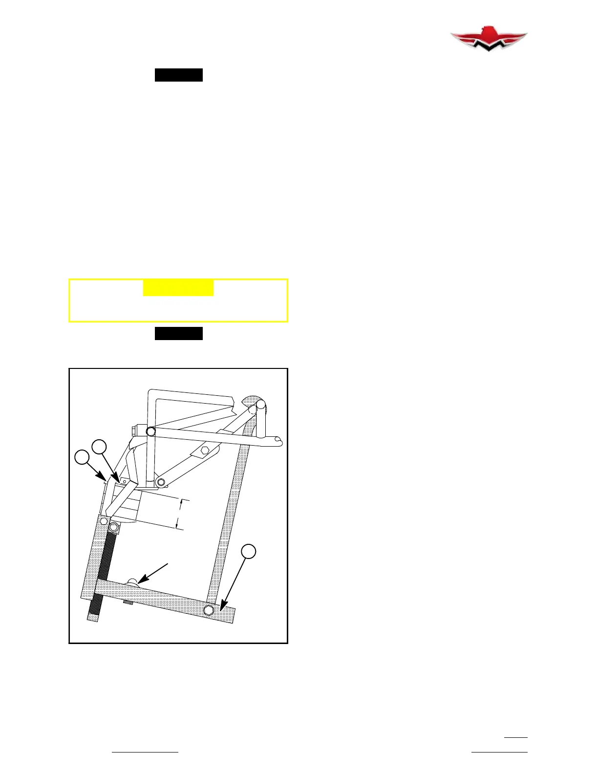
Dimension (T), (F ig. 32- 28), is cri tical to properly
locate nose wheel position. Leg assemblies can
vary, due to manufacturer’s tol erances. Dimen-
sion (T) in a no load fully extended position
should be approximately 3.0 in ches. Add spacer
under collar (D) as needed. See Figure 32- 25,
paragraph 30-50-02, for proper steering/tracking
rigging.
2. Raise aircraft on jacks - shocks fully extended.
A. Inspect nose and main gear shocks for evidence
of gap between retaining collar and retaining plate. The
disc preload must be great enough to maintain com-
plete wheel extension during retraction.
B. Replace shock discs that have lost resilience.
C. Inspect retaining collar and bolt for deformation,
wear, and cracks.
D. Replace defective bolt and collar.
-CAUTION-
Both collar and bolt must be replaced when
one or the other is defective.
-NOTE-
For Nose Gear Steering/Tracking see Section
32-50-02, (Fig. 32- 25).
PAD
T
F
D
E
NOSE GEAR SHOCK DISC REPLACEMENT
FIGURE 32-28
32-82-00 - RECOMMENDED HARD LANDING IN-
SPECTIONS
The following are areas recommended to be inspected
when a “hard landing” or overweight landing has oc-
curred. Since a “hard landing” is a relative term and an
overweight landing may have occurred, it is up to the
owner/operator to advise maintenance personnel
when the inspections are to be accomplished. Howev-
er, since this may be overlooked during preliminary dis-
cussions, the mechanic/technician should inspect the
aircraft for the following:
1. Mud shield missing or damaged on either or both
main landing gear.
2. Main landing gear shock biscuits condition, com-
pressed or extruded rubber.
3. Tail skid damage or damage to bulkhead that at-
taches tail skid.
4. Propeller strike marks or other visual damage.
5. Engine or engine mount damage.
6. Nose landing gear leg assembly damage near
steering lugs.
7. Pilot/Co- Pilot’s seat adjustments supports/tubes
bent from excessive G- loads.
If any evidence of damage or abnormal observations
are found, it is recommended that a thorough inspec-
tion of all the above areas be done and repairs be made
as necessary. Contact FAA personnel for incident re-
port requirements.
32-82-00
 Loading...


