MOONEY INTERNATIONAL CORPORATION
M20V SERVICE AND MAINTENANCE MANUAL
Date
MAR 2017
Rev Date
Page
25
F. Reinstall master cylinder in reverse sequence of
removal.
G. Bleed brake system (refer to Section
12- 20- 05).
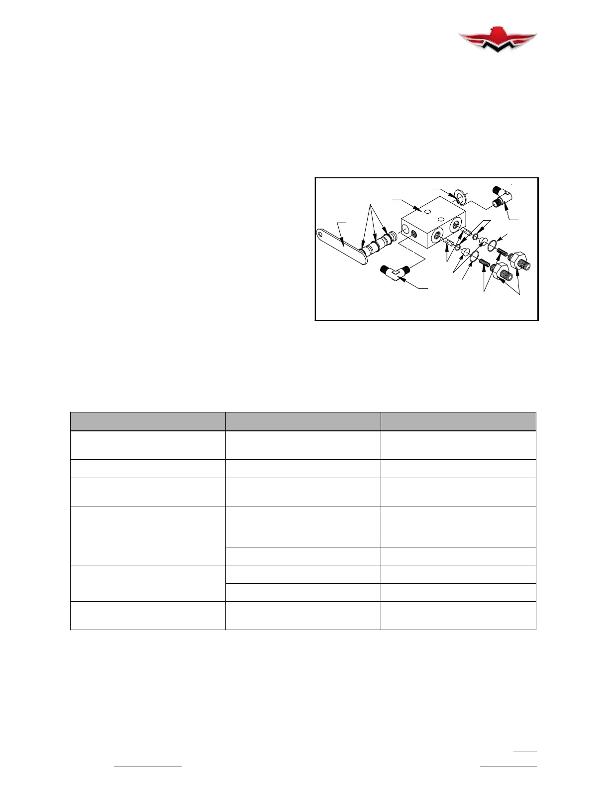
4. PARKING BRAKE VALVE
Removal and disassembly (Fig. 32- 22)
A. Remove forward fiberglass belly skin.
B. Disconnect parking brake control at parking
brake valve arm.
C. Disconnect and cap hydraulic lines.
D. Remove parking brake valve.
E. Disassemble parking brake valve: (Refer Fig.
32- 22).
(1) Remove both fittings (1) from valve housing
(7), springs (8) will come out with the fittings.
(2) Remove poppet valves (2) and pins (3), from
housing by bumping on table top.
(3) Remove both fittings (4) from end of housing.
(4) Remove snap ring (5) from end of camshaft
assembly (6).
(5) Carefully remove camshaft assembly (6)
from housing.
(6) Inspect all components for damage, nicks,
grooves, etc.
(7) Clean all parts with cleaning solvent.
(8) Replace all “O” rings (9).
(9) Reassemble brake valve in reverse se-
quence of disassembly.
(10) Connect valve assembly to the hydraulic
lines.
(11) Bleed sy
stem; service hydraulic reservoir
with hydraulic fluid as described in Section 12-20-05.
6
4
5
7
3
2
8
1
9
4
10
11
9
“O”- RING P/N
9
10
11
MS28775- 012
N507- 90- 006
MS28775- 010
REF:
PARKING BRAKE VALVE
FIGURE 32-22
5. Shuttle Valve - Maintenance
A. No maintenance authorized. Remove and re-
place shuttle valve assembly.
32-41-00 - TROUBLESHOOTING - BRAKE SYSTEM
TROUBLE PROBABLE CAUSE REMEDY
Solid pedal and no brakes. Brake lining worn beyond
allowable limit.
Replace lining.
Spongy brake. Air in system. Bleed brake system.
Pressure will not hold. Leak in brake system. Visually check entire system for
evidence of leaks.
Parking brake will not hold.
Airinsystemorleakinsystem
(downstream of parking brake
valve).
See remedies above.
Defective parking brake valve. Repair or replace the valve.
Brake grabs.
Warped or bent disc. Replace disc.
Foreign matter locking disc. Clean disc and lining.
Brake pedal will not return to
neutral position.
Master cylinder shaft or other link-
age misaligned.
Check that shaft travels in straight
line and not binding in linkage.
32-50-00 - STEERING
32-50-01 - NOSE GEAR STEERING SYSTEM
The nose gear steering system consists of a steering
horn on the gear leg linked to the rudder pedals by
push- pull tubes and bellcranks. Gear retraction auto-
matically disengages the steering mechanism from the
nose wheel. (Section 27- 20- 00 outlines the nose gear
steering rigging.) A centering cam aligns the nose
wheel for entry into the wheel well.
32-41-00
 Loading...


