MOONEY INTERNATIONAL CORPORATION
M20V SERVICE AND MAINTENANCE MANUAL
Date
MAR 2017
Rev Date
Page
24
M. Reassemble brake cylinder assembly and back
lining plate assembly onto the airplane in the reverse
sequence of disassembly.
N. Bleed hydraulic system as described in Section
12- 20- 05.
O. Remove aircraft from jacks.
2. BRAKES - BREAK IN PROCEDURES.
Proper conditioning may be accomplished as follows:
A. Taxi aircraft for 1500 feet with engine at 1700
RPM applying brake pedal force as needed to develop
a 4- 9 knots (5- 10 MPH) taxi speed.
B. Allow the brakes to cool for 10- 15 minutes.
C. Apply brakes and check for restraint at high stat-
ic throttle. If brakes hold, conditioning is complete.
D. If brakes cannot hold aircraft during static run
up, allow brakes to cool completely and repeat steps A
though C.
-NOTE-
Brake pad conditioning is required to properly
cure the resins binding the lining composition
together. Excessive heat created prior to condi-
tioning will carburize the lining material and pre-
vent the attainment of maximum b raking coeffi-
cient.
This conditioning procedure will wear off high spots and
generate sufficient heat to create a thin layer of glazed
material at the lining friction surface. Normal brake
usage should generate enough heat to maintain the
glaze throughout the life of the lining.
3
17
15
16
14
13
11
9
7
6
12
10
5
8
7
4
1
2
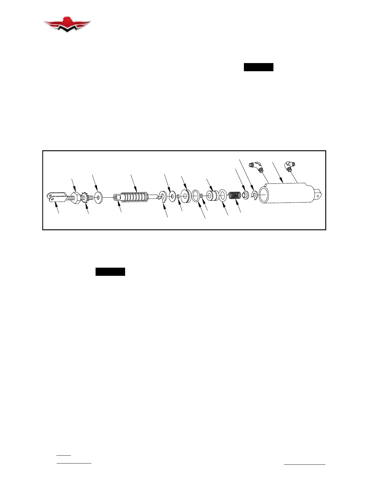
MASTER BRAKE CYLINDERS (PARKER- HANNIFIN 10- 24D SHOWN)
FIGURE 32-21
3. MASTER CYLINDER -
REMOVAL AND DISASSEMBLY (Fig. 32- 21)
-NOTE-
Aircraft have large capacity Master Cylinders
installed.
A. Remove left hand, lower fuselage skin aft of fire-
wall and exhaust cavity.
B. Disconnect hydraulic cylinder from pedal link-
age.
C. Disconnect and cap hydraulic lines.
D. Disconnect hydraulic cylinder from bracket and
remove cylinder.
E. To disassemble master cylinder (Parker- Hanni-
fin, See Fig. 32- 21) Refer to M20V Illustrated Parts
Catalog for Master Cylinder part numbers: Call an
Authorized Mooney Service Center for availability.
(1) Unscrew and remove rod end clevis (17), nut
(16) and washers (14 & 15) from piston rod (13).
(2) Remove snap ring (11) from cylinder housing
assembly; lift out complete piston rod assembly, (items
2 thru 13). Spring (12) can be removed at this time.
(3) Remove snap ring (2) from end of piston rod
assembly.
(4) Remove bushing (3) and spring (4) from end
of piston rod.
(5) Remove piston assembly (5) and “O”- ring (7)
from piston assembly and “O”- ring (6) from piston rod
shaft.
(6) Remove end cap (8) and “O”- rings (9 [ID]
and 7 [OD]) from end cap assembly.
(7) Clean all parts with cleaning solvent.
(8) Inspect cylinder for cracks, scoring, or
grooves in bore.
(9) Inspect piston (5) for damage; check for nicks
and scratches
(10) Inspect end cap (8) for damage.
(11) Inspect push rod for scoring, grooves, nicks
and scratches.
(12) Inspect spring (4) for free height - .500 in.
+/- .030.
(13) Replace all faulty parts and all “O”- rings
(ref. Parker- Hannifin Seal Repair Kit #199- 510).
(14) Reassemble in reverse sequence of disas-
sembly. Immerse all parts in hydraulic brake fluid
(MIL- H- 5606) prior to reassembly.
(15) Check piston rod and return spring (12) for
proper compression during stroke (9 lbs., (initial) to 32
lbs. (@ 3/4 stroke)).
32-40-04
 Loading...


