MOONEY INTERNATIONAL CORPORATION
M20V SERVICE AND MAINTENANCE MANUAL
Date
MAR 2017
Rev Date
Page
23
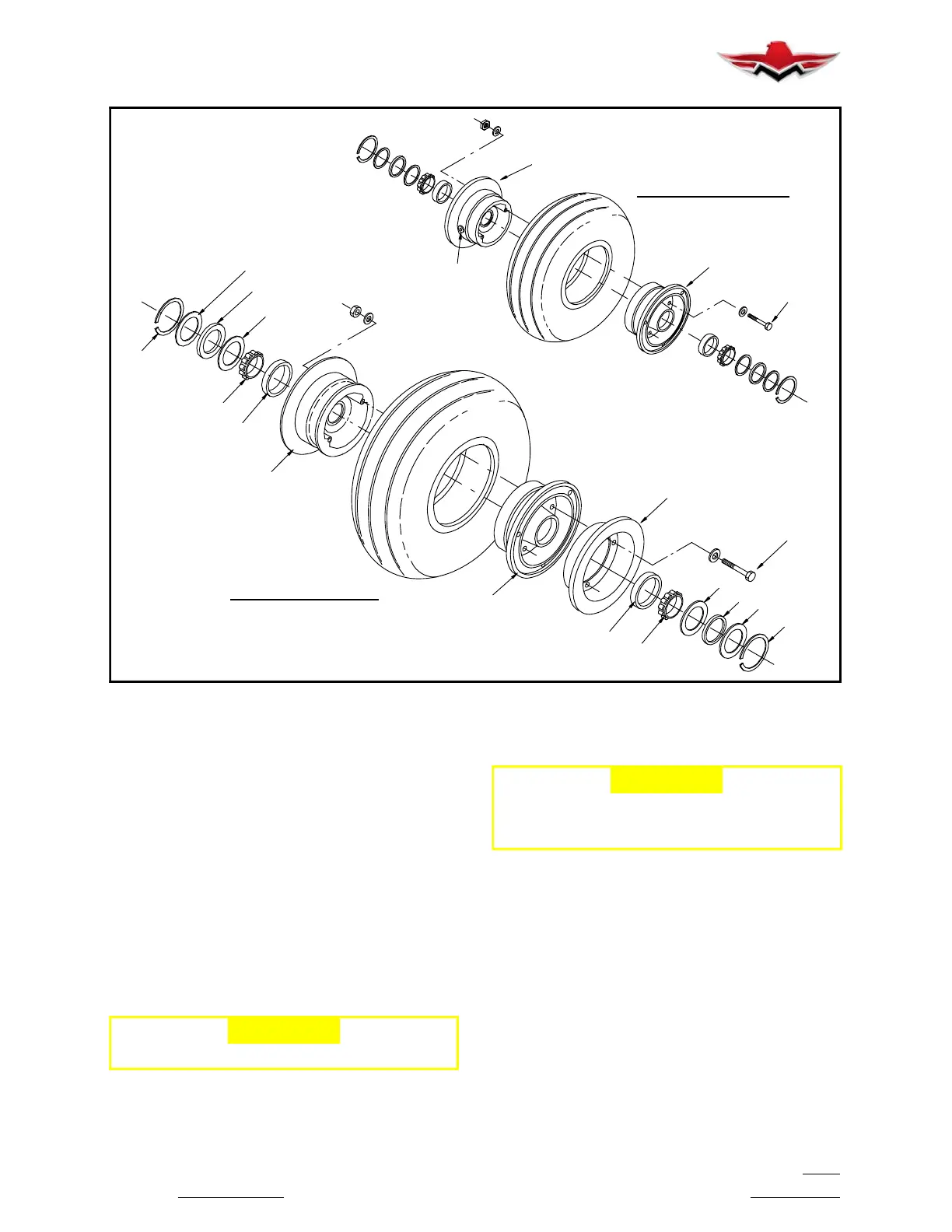
MAIN WHEEL ASSY.
4
3
10
7
7
8
9
8
14
10
7
7
8
8
9
2
5
NOSE WHEEL ASSY.
15
13
15
WHEEL ASSEMBLIES
FIGURE 32-20
E. Remove pressure plate assembly (Fig. 32- 19)
(5) sliding it off the anchor bolts (6). Note the condition
of the anchor bolts. If they are nicked or gouged they
should be sanded smooth to prevent binding with the
pressure plate (5) or torque plate (8). When the anchor
bolts are replaced they should be pressed out. New
ones can be installed by pressing them in place with an
arbor press.
F. Drill out rivets (9) attaching linings (7) to back lin-
ing plate (2) and the pressure plate (5). Remove piston
assembly (10) and “O” ring (11). It is permissible to use
compressed air applied to the brake line fitting to re-
move the piston (10) from the brake cylinder.
-CAUTION-
Do not spin bearing cones with compressed air.
G. Clean parts in cleaning solvent and dry with oil-
free compressed air.
-CAUTION-
Assemble brake on a clean flat surface, being
careful not to nick, scratch or damage protec-
tive finish of brake parts.
H. Replace linings and rivets. Rivet shanks must
be rolled with special tool (Cleveland Rivet Set Kit
#199- 1) for proper installation.
I. Inspect brake cylinder bore for scoring. A scored
cylinder may cause the “O” ring to leak or cause rapid
wear of the “O” ring. A scored brake cylinder should be
replaced.
J. Replace “O” ring (11) with a new one. Do not re-
use the old “O” ring.
K. Lubricate cylinder and piston with MIL- H- 5606
red hydraulic fluid and assemble components with care
to prevent damage to the “O” ring.
L. Service and inspect main wheels as described in
Section 32-40-02.
32-40-04
 Loading...


