MOONEY INTERNATIONAL CORPORATION
M20V SERVICE AND MAINTENANCE MANUAL
Date
MAR 2017
Rev Date
Page
22
9. Replace bearing cones that show signs of wear or
bearing fretting.
10. Repack wheel bearings and lubricate seals with
grease. Install bearings, grease seal rings, and felt
seals in wheel halves. Secure with snap rings.
11. Position tire & tube on wheel half with valve stem
hole; then position other wheel half in tire to match
mounting holes.
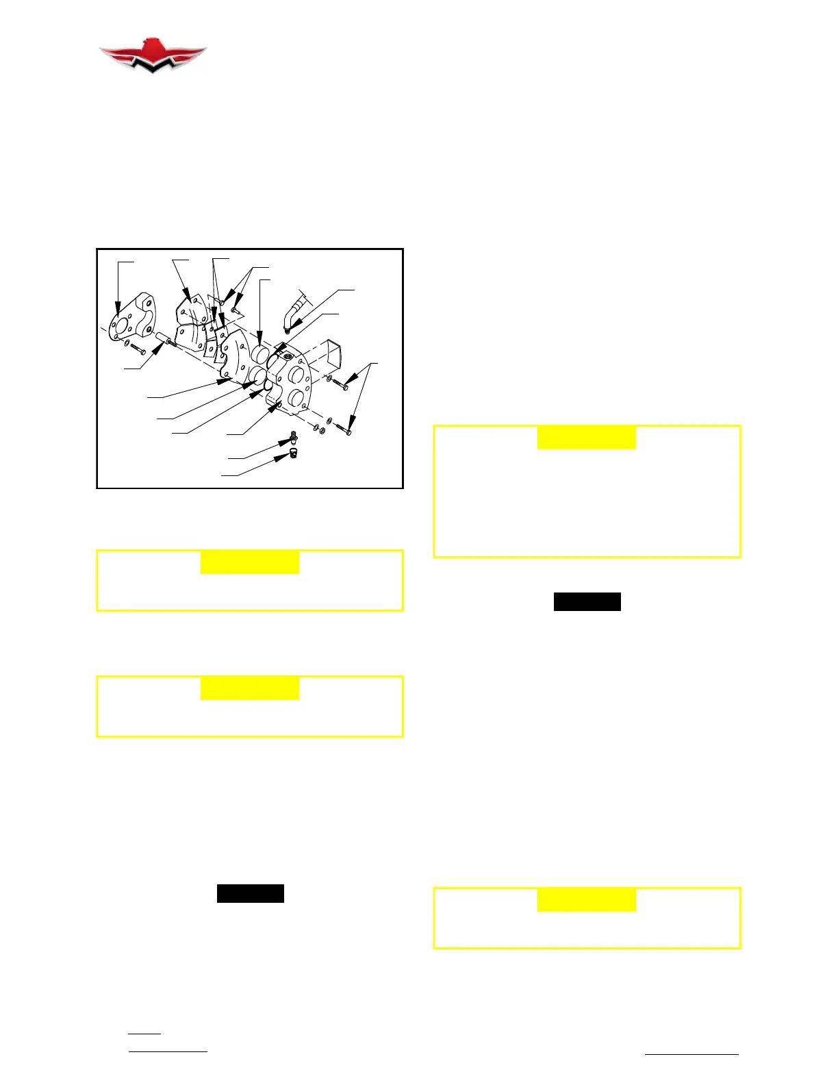
COVER
BLEED VALVE
2
11
10
5
6
8
3
10
7
9
1
11
4
TYPICAL BRAKE ASSEMBLY
FIGURE 32-19
-CAUTION-
Use correct axle spacer to position disc .12
inches from MLG assembly (ref. Fig. 32- 20).
12. Install brake disc (2) (Fig.32- 20) and wheel half
retaining bolts, washers and nuts.
-CAUTION-
Uneven or improper torque may cause bolt or
wheel failure.
13. Tighten nuts evenly and torque to 150 inch
pounds.
14. Inflate tire to 42 PSI.
15. Install wheel assembly, bearing spacer, washer,
and axle nut. Tighten axle nut until bearing binds slight-
ly, back nut off to nearest castellation, and install cotter
pin.
-NOTE-
When properly installed, the wheel will turn with
slight resistance.
16. Install dust shield and IB/MID gear door.
17. Reinstall brake caliper & safety.
32-40-03 - NOSE WHEEL DISASSEMBLY/AS-
SEMBLY
The standard brand, tube- type, 5:00 x 5, Type III, nose
wheel tire is six- ply rated. To remove nose wheel:
1. Remove cotter key, nut, and washer from axle (Fig.
32- 17).
2. Remove nose wheel.
3. Installation is in reverse sequence of removal.
Nose wheel disassembly:
1. Completely deflate tire by removing valve core.
2. Remove nuts, washers, and wheel half retaining
bolts (15) (Fig. 32- 20).
3. Separate wheel halves, (13 and 14) and remove
tire and tube. Refer to Section 32- 40- 02 steps 5 thru
10 for wheel inspection.
4. Reassemble nose wheel in reverse sequence of
removal. Tighten wheel half retaining bolt nuts evenly
and torque to 90 inch- pounds. Inflate tire to 49 PSI.
-CAUTION-
When ANY tire and/or wheel assembly is re-
moved or replaced and re- install ed, conduct
at least 5 complete retraction/extension
cycles to verify tires enter and exit wheel -
wells without interference. Refer to Service &
Maintenance Manual Section 32- 30- 08 for
Final Check procedure.
32-40-04 - BRAKE SYSTEM
-NOTE-
Aircraft have dual puck wheel brake cylinders
installed.
1. BRAKES - REMOVAL AND INSTALLATION
(TYPICAL)
Lining inspection and/or replacement or cylinder repair.
A. Place aircraft on jacks.
B. Remove middle gear doors. Remove safety wire
and two bolts (1) attaching back lining plate assembly
(2) to brake cylinder assembly (Fig. 32- 19).
C. Visually inspect linings for wear and brake disc
for warpage. Brake linings should be replaced when
they are worn to a minimum thickness of 1/8 inch. If lin-
ing replacement is necessary proceed with steps D thru
O. Otherwise reassemble in reverse sequence of dis-
assembly.
-CAUTION-
Brake disc should be replaced if width is .345
in. or less.
D. Disconnect and cap hydraulic line (4) at brake
cylinder assembly. Remove nuts from anchor bolts.
32-40-03
 Loading...


