MOONEY INTERNATIONAL CORPORATION
M20V SERVICE AND MAINTENANCE MANUAL
Date
MAR 2017
Rev Date
Page
10
F
G
J
K
NOSE GEAR RETRACTION TUBE & DOOR AD-
JUSTMENT POINTS
FIGURE 32-9
4. Disconnect nose gear steering horn link (B) (Fig.
32- 8).
5. Remove left and right gear mounting bolts (D) and
(E) (Fig. 32- 5) from tubular structure and nose gear
truss assembly.
6. Carefully remove nose gear assembly.
7. DO NOT attempt to repair heat treated compo-
nents of nose landing gear assembly.
32-20-02 - NOSE GEAR INSTALLATION
1. Lubricate wheel bearings, retraction linkage and
left and right mount bearings.
2. Install gear in reverse order of removal procedure.
3. Torque NLG, steering, pivot bolt (NAS1307- 72D)
and nut (Fig. 32- 23, item 2 & 3) to 270- 375 inch lbs.
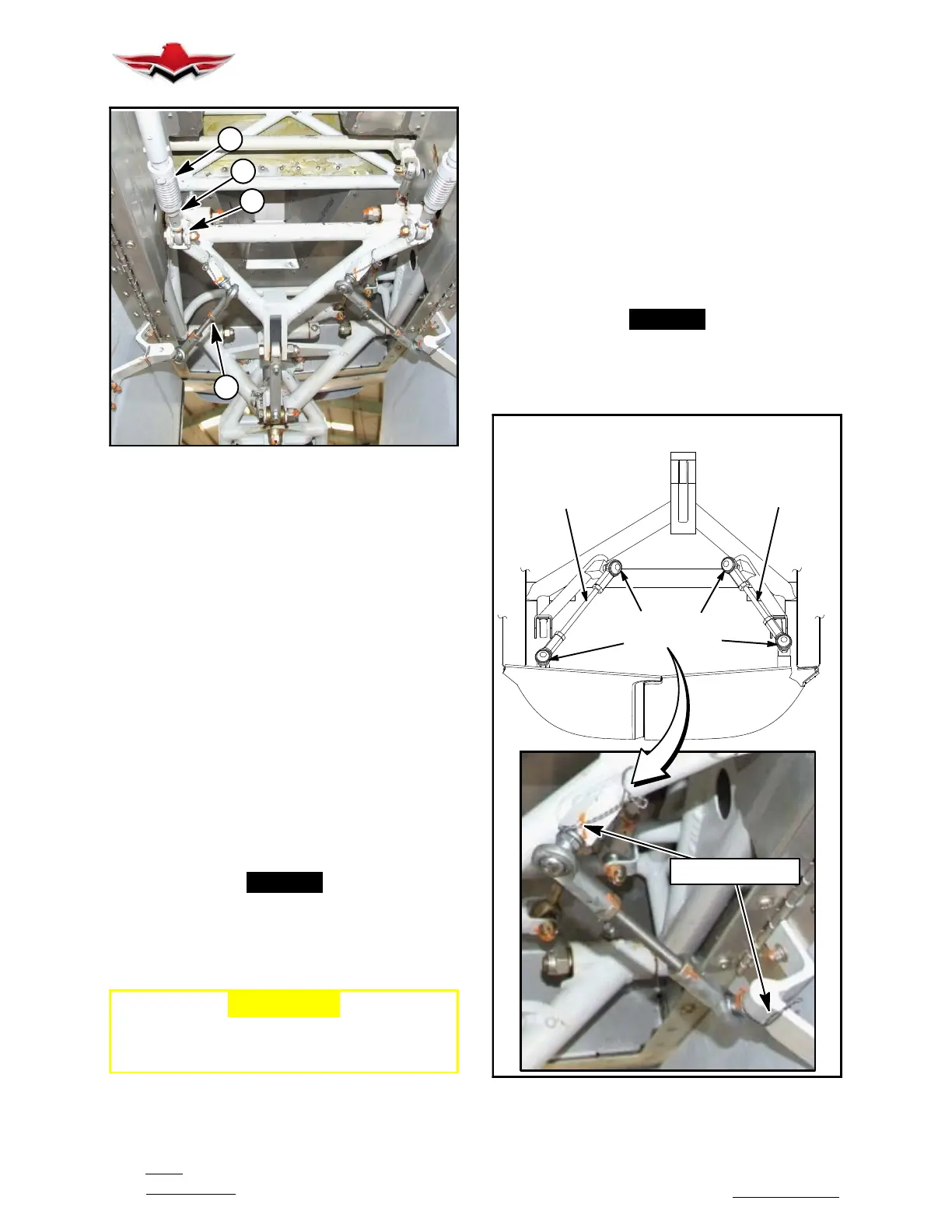
32-20-03 - NOSE GEAR DOOR RIGGING
1.
Raise aircraft on jacks. See Section 7- 10- 00.
-NOTE-
Gear system must be properly rigged prior to
gear door rigging, see Section 32-30-01.
2. Adjust gear door link rods (RH) and (LH) (Fig.
32- 10) to insure snug closure, with zero preload.
-CAUTION-
Nose gear overcenter preload must be
re- checked after any adjustment to nose
wheel eccentrics.
3. Retraction Test with an assistant observing gear
doors:
a. With Aircraft on jacks, push in the Gear actuator
Circuit Breaker.
b. Place the landing gear switch in the up position.
c. Turn the master switch on.
d. Push in the “Red” gear safety bypass switch and
hold it into retract the landing gear, then release the
switch.
e. Turn landing gear switch to the down position and
observe gear doors motion.
f. Turn the master switch off.
-NOTE-
If linkage adjustment is required, make the ad-
justment and go through the procedures until
satisfactory results are obtained, secure with
safety wire.
RH
GEAR DOOR
LH
GEAR DOOR
RH LINK
ADJUST IF REQUIRED
LH LINK
ADJUST IF REQUIRED
FRONT VIEW LOOKING AFT
ROD END AND
SAFETY WIRE
SAFETY WIRE
NOSE GEAR DOORS
FIGURE 32-10
32-20-02
 Loading...


