MOONEY INTERNATIONAL CORPORATION
M20V SERVICE AND MAINTENANCE MANUAL
Date
MAR 2017
Rev Date
Page
11
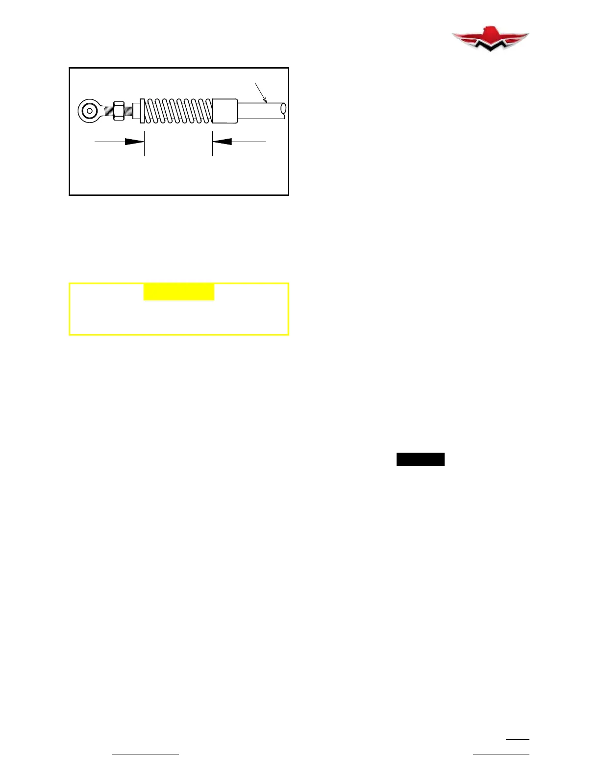
BUNGEE
toriggedpositiontobe.030to.070in.
Deflection of spring from static length
“P”
BUNGEE SPRING
FIGURE 32-11
32-30-00 - EXTENSION AND RETRACTION
32-30-01 - GEAR SYSTEM OPERATIONAL IN-
SPECTION
-CAUTION-
After any abnormal, over gross or hard landing
the Gear System Operational Inspection should
be done.
1.
Raise aircraft on jack
s. (See Section 7-10-00).
2. With Master Switch ON and gear switch in UP
position apply pressure to Pitot tube (see Section
32- 60- 01). Verify gear retraction occurs at 60 +/- 5
KIAS. Allow gear to raise completely. Check for any tire
interference as tire enters wheel well.
3. Close throttle and confirm gear warning “Voice
Alert” sounds.
4. Inspect gear doors for proper closing; lower gear.
5. With zero airspeed place gear switch in UP posi-
tion, Gear warning should sound regardless of throttle
position. Both gear position lights and light within safety
bypass switch will illuminate.
6. Push RED gear safety bypass switch and hold IN
to partially retract gear.
7. Pull “GEAR ACT” circuit breaker.
8. Check nose gear overcenter preload as follows:
A. Measure nose gear bungees. (No load)
(Fig. 32- 11).
B. Extend gear manually (See Section 32-30-07)
s
topping extension the moment the GREEN Gear
Down Light comes ON. Gear switch in DOWN position.
C. Measure nose gear bungee springs
(Fig.32- 11). Deflection from zero load condition in (A)
above must be .030 to .070 inches for each bungee.
D. If spring deflection is not within prescribed limits,
adjust tube rod ends (F) (Fig. 32- 9) in increments of 1/2
turns as required.
9. Check main gear overcenter preload.
A. Place rigging tool (T) P/N GSE 030007 (Fig.
32- 1) on retraction truss. Hold tool stationary by plac-
ing thumb on rear end of tool (S) and press forward.
B. Hold 10” torque wrench (R) and place thumb on
wing bottom; apply force until joint (4) breaks open
slightly, insert shim stock (.005 .008 in. thickness) be-
tween link and truss at (P). Release force on wrench.
C. With fingers on torque wrench and thumb on
wing bottom apply force on wrench while maintaining a
pulling force on shim stock. Read torque value on
wrench at the exact moment the shim stock pulls loose.
Torque value should be 250 to 280 inch pounds.
D. Repeat on other side’s main gear.
E. If preload is not within prescribed limits; proceed
to Main Landing Gear Rigging procedures, Section
32- 30- 02.
F. If main gear preload needs re- adjusting, the
nose gear bungees should be re- checked per 8, (C)
above (Fig. 32- 11) after re- adjustment is completed.
-NOTE-
When gear overcenter preload check is com-
pleted, electrically extend the gear and check the
nose gear tube bungee springs to assure they
have not compressed completely resulting in no
remaining deflection. This would indicate exces-
sive preload or weak bungees.
32-30-00
 Loading...


