MOONEY INTERNATIONAL CORPORATION
M20V SERVICE AND MAINTENANCE MANUAL
Date
MAR 2017
Rev Date
Page
12
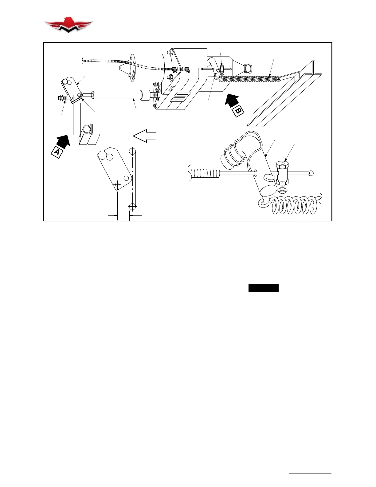
DETAIL “A”
F
1.56 IN. (APPROX.)
FUS. STA. 33.0
FWD
N
D
A
DETAIL “B”
B
C
B
E
C
N
LANDING GEAR ACTUATOR ADJUSTMENTS
FIGURE 32-12
32-30-02 - MAIN LANDING GEAR SYSTEM RIG-
GING
Changing eccentric bearing position can change
deflection on bungee spring. Shortening tube assem-
bly creates compression on bungee (refer to Fig.
32- 11).
1. Raise aircraft on jacks and remove smooth belly
access panel(s).
If Assist Bungee removal is required, see procedure in
32- 10- 06.
2. Pull landing gear actuator circuit breaker out.
3. Loosen jam nuts (E) on main retraction tubes (L),
Fig.32- 4; disconnect tubes at inboard bellcranks (M).
4. In nose gear well, loosen jam nuts (G) (Fig.32- 9)
on nose gear retraction tubes (F).
5. At main retraction bellcrank (A) (Fig.32- 12) dis-
connect nose gear retraction tubes and actuator barrel
nut at (N) (Fig. 32- 12).
6. Check dimension from rod end center to the end of
the barrel nut housing on actuator to be 1.25
+.000/- .010. Adjust rod end bearing, if necessary, and
secure with set screw and jam nut.
7. Disconnect nose gear doors, outboard main gear
doors, and inboard door links. On outboard main gear
doors, disconnect springs. On inboard door bellcranks,
disconnect springs. Loosen jamb nut (X) on retraction
tube (V) (Fig.32- 1) and back off pressure on spring (W)
by loosening nut (Y). Disconnect retraction tube (V)
from bellcrank C (Fig. 32- 5).
8. Position main retraction bellcrank (A) so center of
forward hole in left outboard arm of bellcrank is 1.56 ***
inches from forward face of truss at F.S. 33 (Fig.32- 12,
Detail A).
-NOTE-
This dimension *** may vary to permit connection
of retraction tubes with zero preload at bolt hole.
9. With main retract bellcrank held in position, turn
actuator barrel nut until rod end bearing aligns with hole
in bellcrank; install connection bolt at (N) (Fig. 32- 12).
10. Position bellcrank (C) (Fig. 32- 5), so center of at-
tach pin (D) on top leg is 1.35 inches from bottom side of
spar cap (E). This will be the starting position when
landing gear is in down and locked over center, with out
any preload set.
11. Adjust retraction tube (V) (Fig. 32- 1), at rod end,
until it will connect to bellcrank (C) (Fig. 32- 5) with zero
preload. Install connection bolt/hardware; leave loose
at this time.
12. Adjust rod end on retraction tube (L) (Fig. 32- 4)
so attach hole is aligned with inboard bellcrank at (M).
Install connection bolt/hardware.
13. Disconnect retraction tube (V) at bellcrank (C)
rod end; position disconnected gear full down and
locked over center. Both LH and RH landing gear
should be in this configuration at this time.
32-30-02
 Loading...


