MOONEY INTERNATIONAL CORPORATION
M20V SERVICE AND MAINTENANCE MANUAL
Date
MAR 2017
Rev Date
Page
13
14. PUSH landing gear actuator C/B – IN.
15. Turn MASTER Switch – ON.
16. Extend main gear actuator to fully extended posi-
tion. Make certain lugs on main retract bellcrank do not
contact fuselage tubes, floorboard or actuator barrel
nut. If there is any contact, run actuator back up slightly.
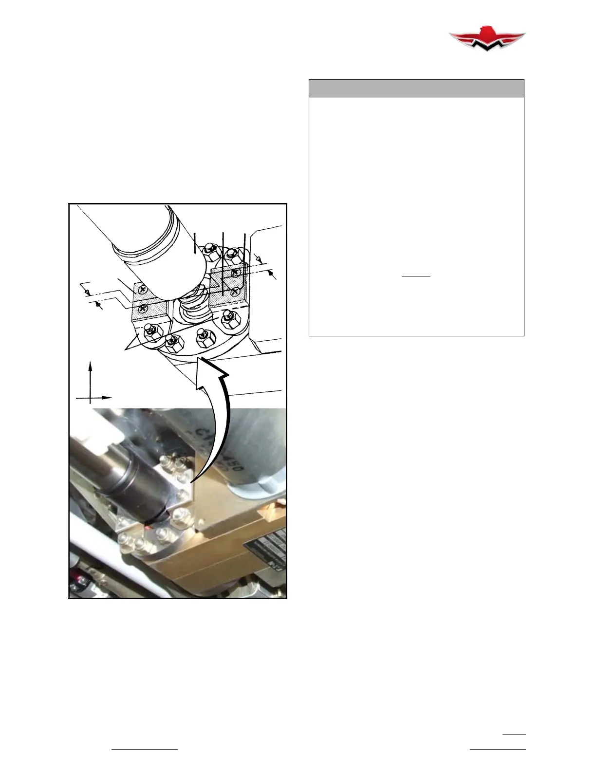
MECHANICAL DOWN STOP ADJUSTMENT
17. There should be .050 to .100 inch clearance (B)
obtained between actuator barrel (C) (Fig. 32- 13) and
mechanical down stop (A). Shims (D) (Fig. 32- 13) may
be added to the mechanical downstop (A) (4 max).
B
D
A
C
D
E
UP
OUTBD
B
MECHANICAL DOWN STOP
FIGURE 32-13
LEGEND FOR FIGURE 32- 13
A. 560252-009 Adjustable Stop (use 560252-011
Shims)
Use one DOWN STOP on each side as required
(Pick up existing hardware)
B. .050 - .100 clearance (between Down-Stop
and end of Ball Nut)
C. Actuator Ball Nut
D. 560252-011 Shims * (use 560252-009, maxi-
mum of 4)
E. AN515-6R Screw **
AN936A6 Lock Washer
(Typ. 2 plc.) (use 560252-009)
F. Loosen Set Screw (C) (Fig. 32- 15)
NOTE:
* Use 1 to 4 560252-011 Shims with 560252- 009
Stop to achieve proper clearance
** Use .063 longer screws with each additional
shim. (Secure screw with Blue Loctite #83-31
Grade C)
18. Run actuator down and recheck retraction bell-
crank clearance at F.S. 33. Check clearance of bell-
cranks (M) (Fig.32- 4) and center section.
19. Reconnect retraction tubes (V) (Fig. 32- 1). With
main gear fully extended, if necessary, adjust main
gear retraction tubes (L) (Fig.32- 4) so they are con-
nected with zero preload.
20. Adjust nut (Y) of retraction tube (V) (Fig. 32- 1)
until main gear is preloaded. Preload is correct when a
“clean break” can be felt when pushing UP on retraction
link (Fig. 32- 1).
21. NOSE GEAR RETRACTION TUBES ARE TO
REMAIN DISCONNECTED at main retraction bell-
crank (A) (Fig. 32- 12) during remainder of procedures.
22. Place landing gear switch in UP position.
23. PUSH RED gear safety by- pass switch IN inter-
mittently to “BUMP UP” (retract) landing gear until left
main tire just contacts bumper bracket which covers
bulb stringer in wheel well. Make certain actuator barrel
does not contact main retract bellcrank in UP position.
24. Set UP limit switch paddle (striker arm) (H) (Fig.
32- 4) so GEAR UP limit switch is just CLOSED and
RED “GEAR UNSAFE” light is OFF. Secure striker arm
in position.
32-30-02
 Loading...


