MOONEY INTERNATIONAL CORPORATION
M20V SERVICE AND MAINTENANCE MANUAL
Date
MAR 2017
Rev Date
Page
14
B
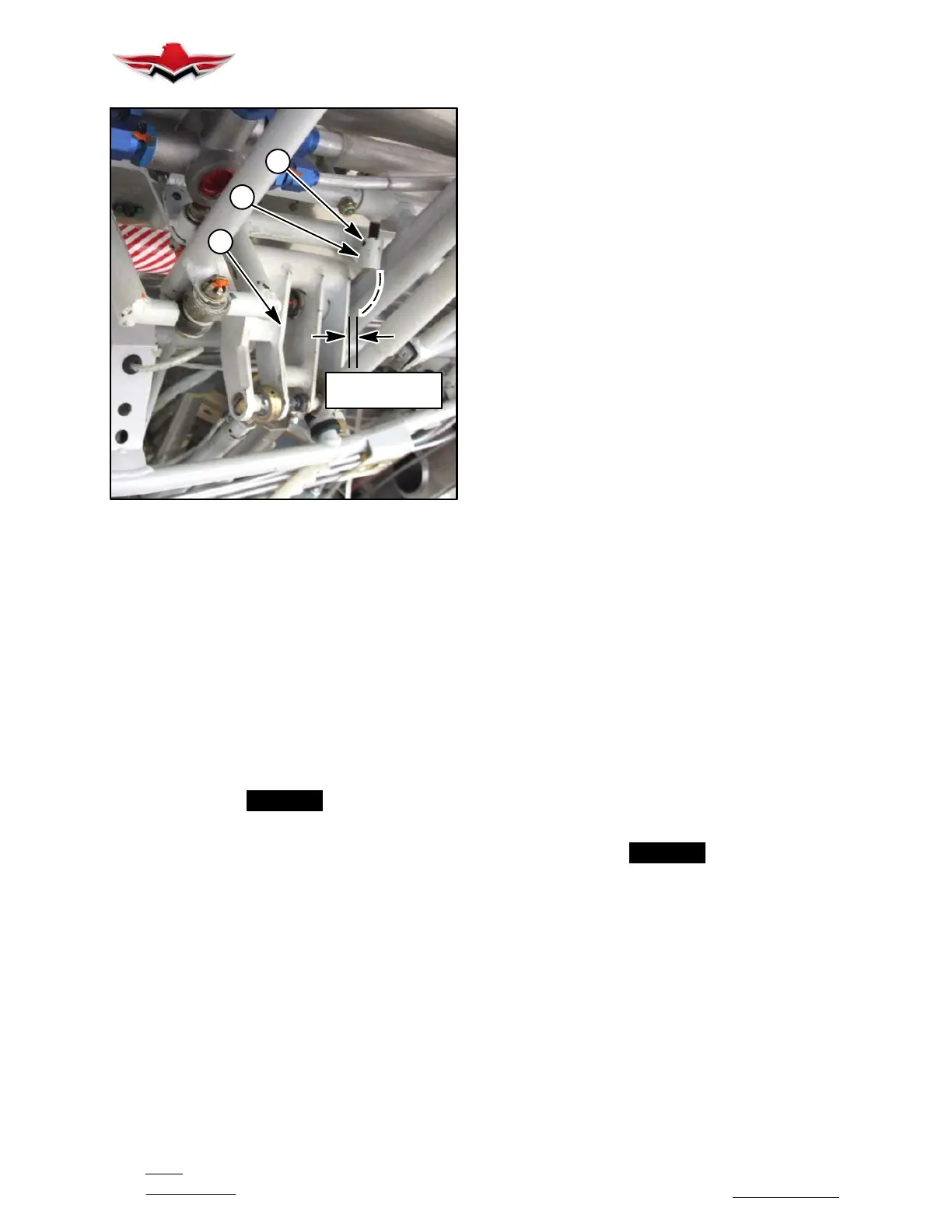
A
C
.050” to .070”
CLEARANCE
MECHANICAL UP STOP
FIGURE 32-14
MECHANICAL UP STOP ADJUSTMENT
25. Loosen set screw (C) (Fig. 32- 14). Adjust me-
chanical up- stop (A) (Fig. 32- 14) for a clearance of
.050 to .070 inches at main retraction truss (B); tighten
set screw (C).
26. Reinstall assist bungee per Section 32- 10- 06.
27. Using emergency gear extension, move gear
down until GREEN gear down light JUST illuminates.
28. Turn Master Switch –OFF.
-NOTE-
The left main gear truss will probably lock over
center first. Continue to slowly lower gear manu-
ally while monitoring compression of bungee
spring on retraction tubes (V) (Fig. 32- 1). If
spring coils are fully compressed, retract tube (V)
must be removed from aircraft for modification:
Dismantle bungee portion of tube (V); remove
one space washer (Z) and reassemble. Re- install
modified retraction tube and complete above
overcenter requirement. The removal or addition
of spacer washers may be required prior to ob-
taining final confi guration for the retraction tube
(V).
29. Place rigging tool (T) (Fig. 32- 1) P/N
030007- 100 on retraction truss assembly (G). Hold
tool stationary by pushing at point (S) toward main gear
leg.
30. Place 10 inch torque wrench (R) on rigging tool
(T) as shown in Figure 32- 1 and apply an unlocking
force to retraction truss.
31. When joint at (4) breaks open slightly, insert shim
stock (.005 to .008 in. thickness) between retraction
link and truss at (P), then release force on torque
wrench.
32. While applying a pulling force on the shim stock,
exert an increasing unlocking force with torque wrench.
33. Read torque wrench value at the EXACT mo-
ment shim stock pulls loose.
34. Repeat steps 30 through 34 on other side’s main
landing gear leg.
35. Use adjusting nuts (Y) on retract tubes (V) to
equalize breakaway torque values within 10.0 inch lbs.
Adjust torque to 250 to 280 inch lbs (Ref. Fig. 32- 1).
36. Turn Master Switch – ON.
37. RUN GEAR DOWN ELECTRICALLY AND
CHECK THAT TORQUE VALUES DO NOT EXCEED
325 INCH POUNDS USING TORQUE WRENCH/
SHIM STOCK METHOD.
GEAR WARNING ADJUSTMENT
1. Check that landing gear warning light circuit break-
er is pushed – IN.
2. Check that landing gear actuator circuit breaker is
pulled – OUT.
3.TurnMasterSwitch–ON.
4. Set DOWN limit switch paddle (striker arm) (J)
(Fig. 32- 4) so that gear down limit switch is just
CLOSED and GREEN “GEAR DOWN” light is ON. Se-
cure striker arm in position.
5.TurnMasterSwitch–OFF.
-NOTE-
The main gear preload torque should not exceed
325 inch lb. using the torque wrench/shim stock
procedure after electrical extension.
The main landing gear system is now rigged for the
gear down and locked condition.
32-30-03 - NOSE LANDING GEAR RIGGING PRO-
CEDURE
1. Check the eccentric bushings, two on LH and two
on RH retract clevis, (J) (Fig. 32- 9) on nose gear truss
assembly to be installed with bolt hole at the upper for-
ward position or, to position nose wheel at top of wheel
well.
32-30-03
 Loading...


