MOONEY INTERNATIONAL CORPORATION
M20V SERVICE AND MAINTENANCE MANUAL
Date
MAR 2017
Rev Date
Page
15
-CAUTION-
The eccentric bushing, on either or both sides,
maybecountersunkandhaveaflushhead
screw installed to allow clearance of nose gear
truss during retraction/extension cycle. This
configuration MUST be maintained during any
removal/installation action for the truss or ec-
centric bushing.
2. Adjust nose gear retraction tubes (F) (Fig. 32- 8)
so they can be reconnected to the main retraction bell-
crank with zero preload.
-NOTE-
The eccentric bushings may require rotating to a
new position in order to meet zero preload condi-
tion.
3. Measure nose gear bungees dimension (P) (Fig.
32- 11) and record for future reference.
4. Push landing gear actuator C/B – IN.
5. Place landing gear switch in the UP position.
6. Turn Master Switch – ON
7. Push RED GEAR SAFETY BY- PASS SWITCH –
IN and hold IN to partially retract landing gear; release
switch.
8.TurnMasterSwitch–OFF.
9. Pull landing gear actuator C/B – OUT.
10. Screw each nose gear retraction tube (F)
(Fig.32- 8) IN (clockwise looking toward the front of the
aircraft) one (1) full turn, then re- attach to main retrac-
tion bellcrank.
11. Place landing gear switch in DOWN position.
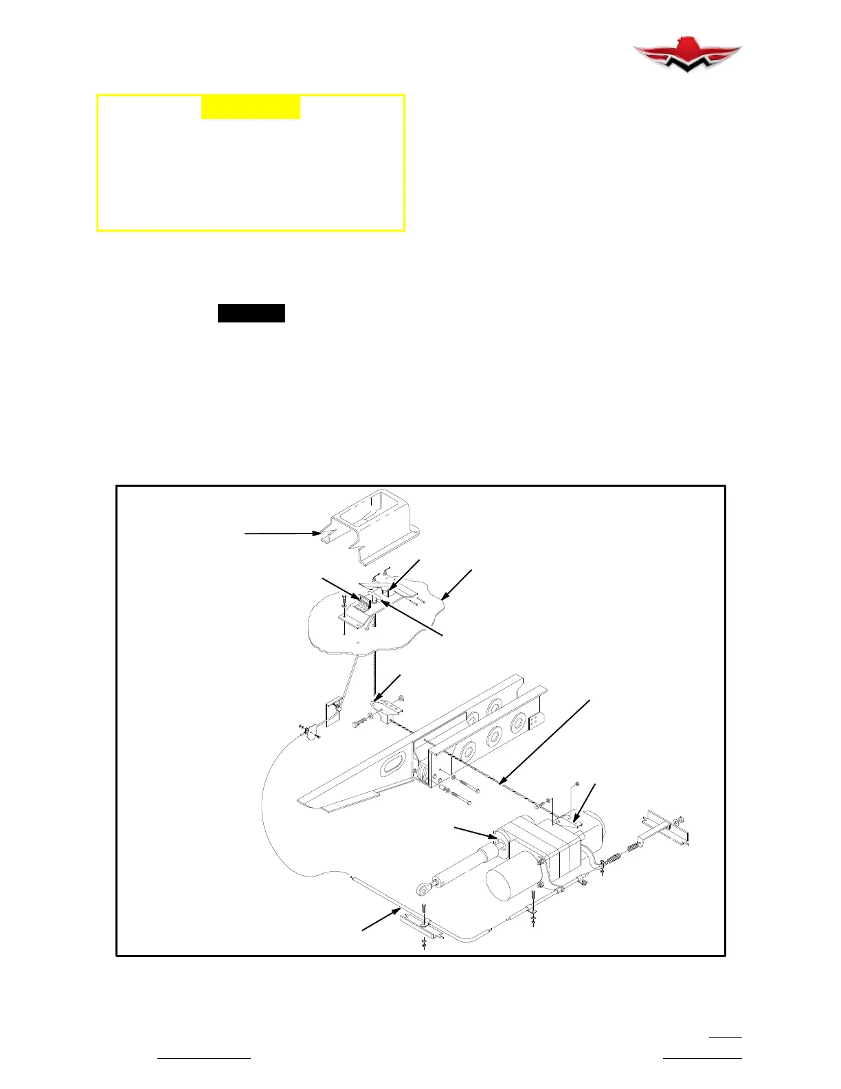
12. Push latch (5) (Fig. 32- 15) FORWARD on manu-
al emergency extension controls (on floorboard).
13. Pull RED lever (1) (Fig. 32- 15) back and upward
to engage manual emergency gear extension system.
14. Pull “T” handle (2) UP (slowly until engaged) and
return it to its original position. Continue this procedure,
stopping when the gear down light JUST illuminates.
15. Measure nose gear bungee assemblies dimen-
sion “P” as shown in Figure 32- 11. If the springs have
deflected less than .030 inches or more than .070 inch-
es from the static dimension (as recorded in Step 2),
adjust the length of the bungee assembly’s to bring the
deflection within tolerance.
DISENGAGE
CABLE ROUTING
ACTUATOR
FLOORBOARD
5
COVER
3
2
1
RETRACTION
4
CABLE
EMERGENCY GEAR EXTENSION SYSTEM
FIGURE 32-15
32-30-04
 Loading...


