MOONEY INTERNATIONAL CORPORATION
M20V SERVICE AND MAINTENANCE MANUAL
Date
MAR 2017
Rev Date
Page
16
32-30-04 - EMERGENCY GEAR EXTENSION SYS-
TEM RIGGING
DISENGAGE RIGGING:
1. Insert cable through hole in actuator disengage
arm, (B) (Fig. 32- 12).
2. With RED lever (1) (Fig. 32- 15) in full disengaged
position (down and latched), push actuator disengage
arm (B) (Fig.32- 12) to full forward position and apply
approximately 5 lbs. pull to cable to remove slack.
3. Install D222 wire stop, (C) (Fig. 32- 12, Detail B)
tighten nut and connect spring (E) to clevis pin, (D).
4. Lift RED lever and pull “T” handle (2) (Fig. 32- 15)
aside; re- engage RED lever. Check manual extension
system to verify that it is fully disengaged by pulling “T”
handle; no resistance should be felt. If a resistance is
felt check cable routing through pulleys (3 & 4) (Fig.
32- 15)
to verify whether it is cable routing or actuator resist-
ance.
5. Move RED lever to full UP position; pull “T” handle
slowly to verify manual extension system is engaged.
Resistance should be felt at once.
6. Replace “T” handle under RED lever and return
RED lever to disengage position, (down and latched).
Manual extension system is now rigged.
5
12
14
3
4
1
MOD. IDENTIFICATION
(P/N 102000- ( X))
EATON ACTUATOR
13
11
8
7
2
9
10
15
16
6
5A
5B
5C
PLATE
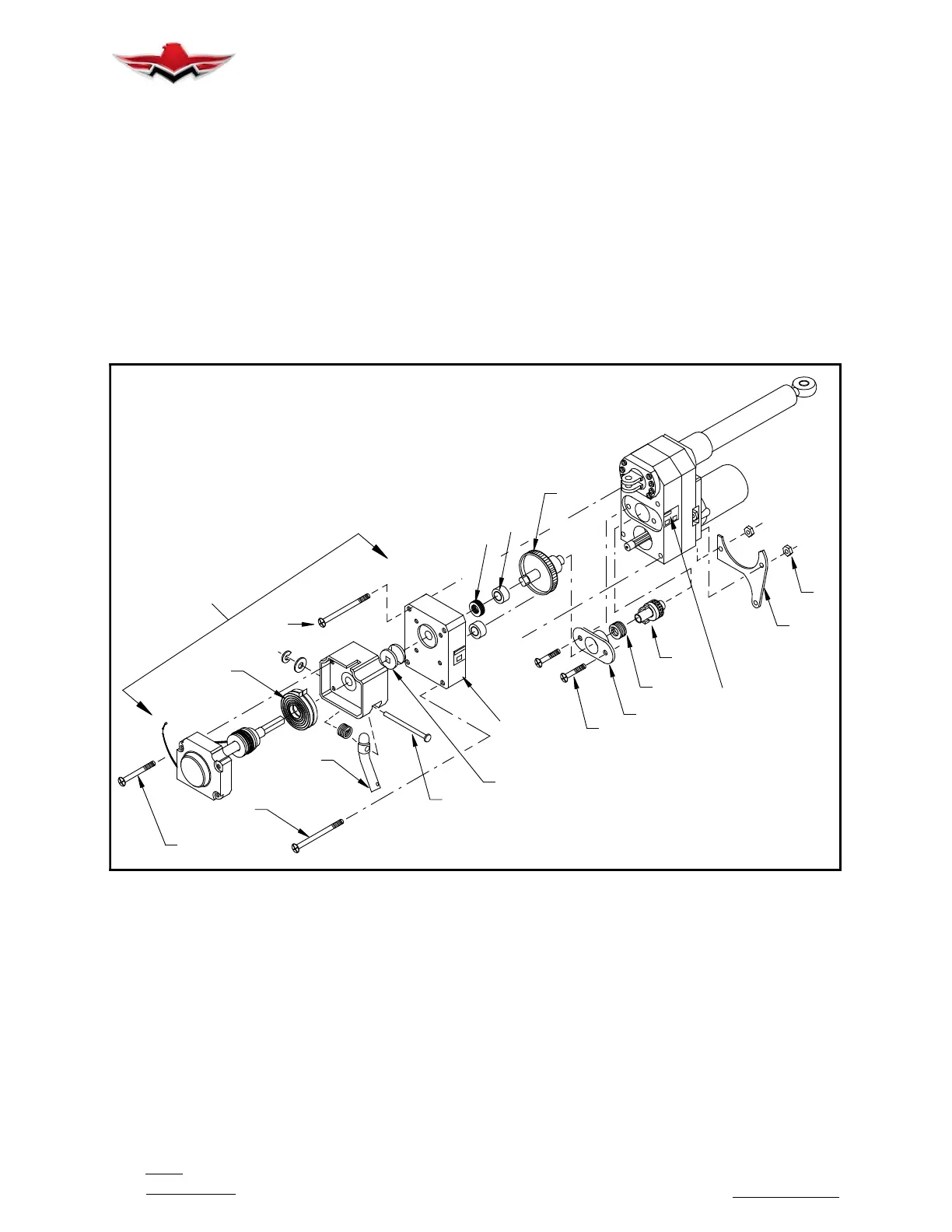
LANDING GEAR ACTUATOR (EXPLODED VIEW)
FIGURE 32-16
32-30-05 - LANDING GEAR ACTUATOR, CLUTCH
SPRING REPLACEMENT
Landing gear actuator clutch spring replacement is
mandatory at each 1000 hours of aircraft operation for
Eaton actuators.
ACTUATOR REMOVAL FROM AIRCRAFT
1. Jack aircraft in accordance with Section 7- 10- 00.
Belly panels should be OFF.
2. Partially retract landing gear from the overcenter
position.
3. Loosen set screw on emergency “T” handle/cable
on cabin floor. Pull cable from handle.
4. Remove two nuts, (1) (Fig. 32- 16); note position of
cable support bracket (2) and remove.
5. Remove manual extension system disengage
cable from actuator disengage arm (ref. Fig. 32- 12).
6. Remove bolt from Heim bearing at retract bell-
crank.
7. Disconnect electrical connection from actuator.
8. Remove bolt from lug at Hat Section.
32-30-05



 To Next Page